Vision auxiliary tool
An auxiliary tool and vision technology, which is applied in the direction of TV, color TV, closed-circuit television system, etc., can solve the problems of inconvenient carrying, single auxiliary function, complex operation of vision aids, etc., and achieve simple structure, good visual effect, and time control short effect
- Summary
- Abstract
- Description
- Claims
- Application Information
AI Technical Summary
Problems solved by technology
Method used
Image
Examples
Embodiment 1
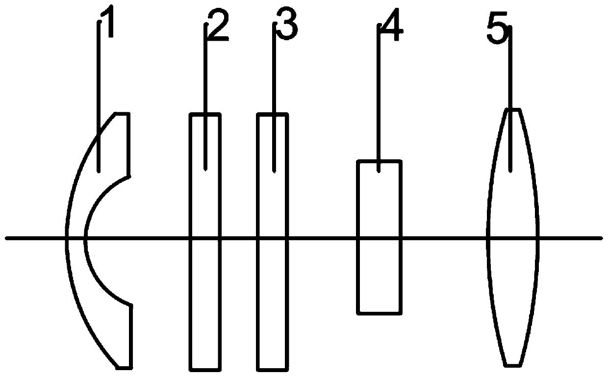
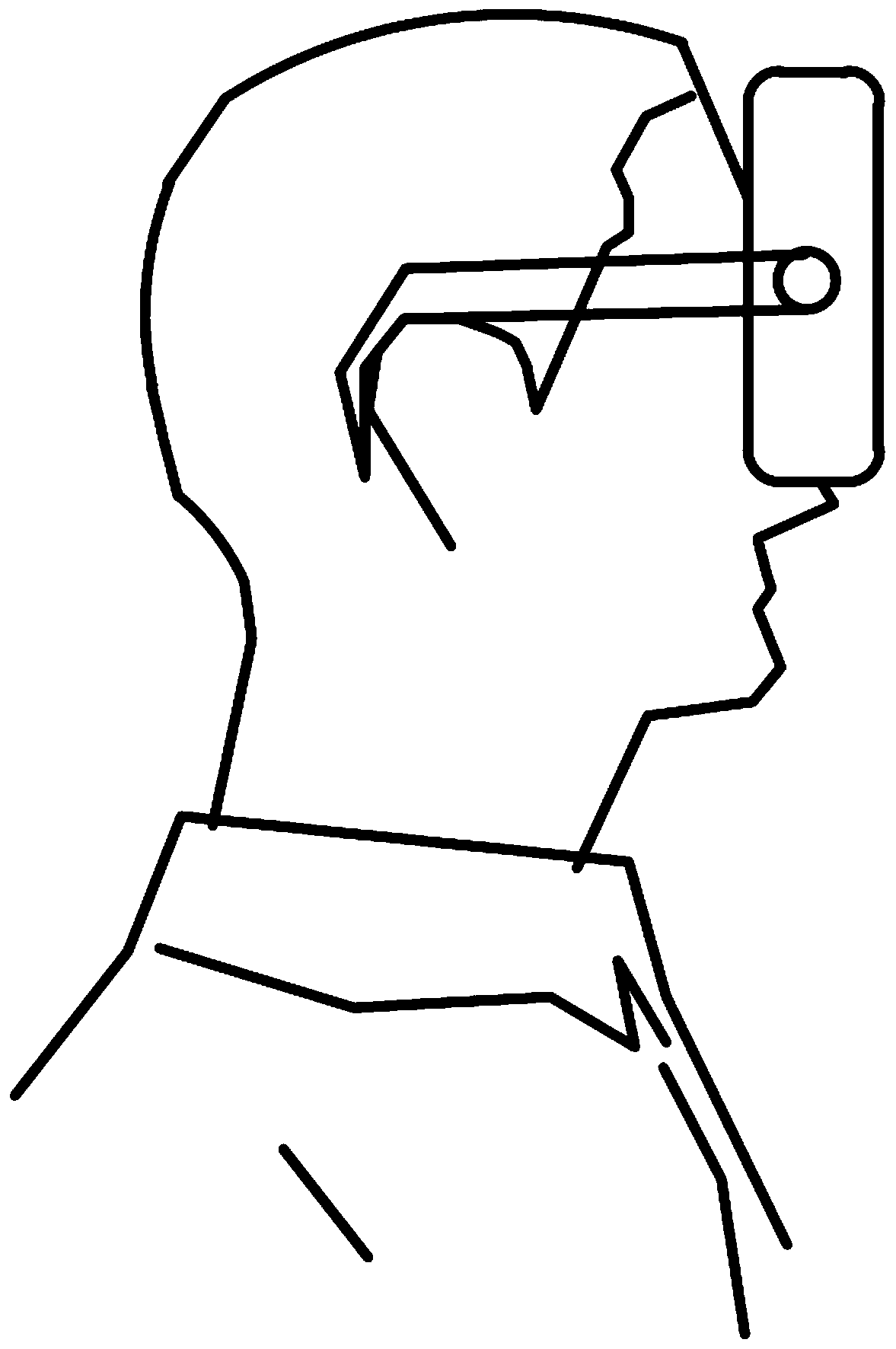
[0040] As shown in the figure, a vision aid includes a housing 6 worn on the head, a camera 1, a display screen 4, a micro power supply, a zoom component, a circuit board, and a switch are arranged on the housing 6 Button 8; the camera 1 is divided into a left-eye camera and a right-eye camera, the size of which is just in line with the embedding of the housing 6, and will be fixed on the front end of the housing 6 away from the eyes, for acquiring images and feeding them back to the display screen 4; The display screen 4 is also divided into a left display screen 4 and a right display screen 4, and is fixed behind the camera 1 for displaying images obtained by the camera 1; The display screen 4, the micro power supply, the zoom component, and the switch are electrically connected; the micro power supply is integrated inside the housing 6, at the rear of the circuit board, for storing and providing electric energy; the zoom component is arranged inside the housing 6 to obtain a...
Embodiment 2
[0043] On the basis of embodiment 1, the circuit board of the present invention is also soldered with a PLC controller, its model is Siemens S7-200, CPU 211, it should be noted here that other controllers that meet the requirements of this application are also available within the selected range.
[0044] The interior of the housing 6 is also equipped with a convex lens 5, which is arranged behind the display screen 4 to change the distance and range of human eyesight; in addition, the micro power supply is a rechargeable battery, and two ends of the housing 6 are provided with The legs 7 are movably connected with the housing 6 respectively, and are used to fix the vision aid on the human ear.
[0045] When in use, place the two supporting legs 7 of the device on the user's ears respectively, then turn on the switch button 8, and the whole device is turned on. After the camera 1 acquires the image, the image is adjusted clearly through the zooming part, and the image is clear...
Embodiment 3
[0048] On the basis of Embodiment 1, the zoom component includes a focus adjustment knob 2 and an automatic focus component; the focus adjustment knob 2 is fixed between the display screen 4 and the camera 1, and is electrically connected with the circuit board and a micro power supply for Adjust the size and definition of the image; the automatic focusing component circuit board is electrically connected to adjust the focal length of the camera 1 to make the image of the display 4 clearer, and a screen brightness adjustment knob is fixed between the display 4 and the focus adjustment knob 2 3. It is connected with the circuit board and the display screen 4 for adjusting the brightness of the screen.
[0049]The interior of the casing 6 is also equipped with a convex lens 5, which is arranged behind the display screen 4 to change the distance of human eyes; , are movably connected with the housing 6 respectively, and are used to fix the vision aid on the human ear.
[0050] W...
PUM
 Abstract
Description
Claims
Application Information
 - R&D
- Intellectual Property
- Life Sciences
- Materials
- Tech Scout
- Unparalleled Data Quality
- Higher Quality Content
- 60% Fewer Hallucinations
Browse by: Latest US Patents, China's latest patents, Technical Efficacy Thesaurus, Application Domain, Technology Topic, Popular Technical Reports.
© 2025 PatSnap. All rights reserved.Legal|Privacy policy|Modern Slavery Act Transparency Statement|Sitemap|About US| Contact US: help@patsnap.com


