Vertical water-stop structure and construction method thereof for water conservancy projects

A vertical water stop and water conservancy engineering technology, applied in water conservancy projects, sea area projects, dams, etc., can solve problems that threaten life and property safety, consume a lot of physical strength and time, and slow rescue speed, so as to reduce contact area and friction force , the effect of not easy to get stuck

Active Publication Date: 2021-06-08
宁夏晋明建设工程有限公司
View PDF11 Cites 0 Cited by
  • Summary
  • Abstract
  • Description
  • Claims
  • Application Information

AI Technical Summary

Problems solved by technology

[0003] At present, some vertical concrete structures are used on both sides of the river in some parks and scenic spots to retain water and reduce soil loss. However, the height of the existing vertical concrete structures is fixed. When encountering floods, Floods can easily overturn the vertical concrete structure and pose a threat to people's lives and property. In the patent with the publication number CN110016889A, a vertical water-stop structure is proposed. When a flood occurs, the waterproof plastic cloth is pressed under the partition and the joint is sealed to achieve the purpose of temporarily increasing the waterproof height. However, it takes a lot of physical strength and time to complete the above-mentioned series of processes manually. , if the rescue personnel are scarce or the rescue speed is slow, the flood will break through the water-stop structure, threatening the safety of people's lives and property. Therefore, we propose a vertical water-stop structure for water conservancy projects and its construction method

Method used


Image

  • Vertical water-stop structure and construction method thereof for water conservancy projects
  • Vertical water-stop structure and construction method thereof for water conservancy projects
  • Vertical water-stop structure and construction method thereof for water conservancy projects

Examples


Embodiment Construction

[0036] The following will clearly and completely describe the technical solutions in the embodiments of the present invention with reference to the accompanying drawings in the embodiments of the present invention. Obviously, the described embodiments are only some, not all, embodiments of the present invention.

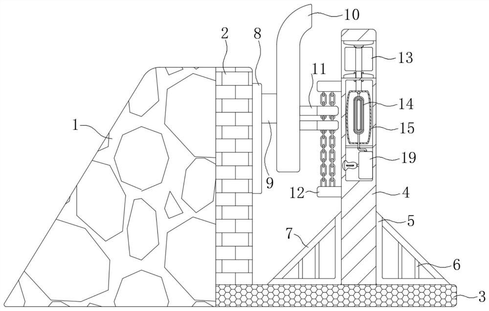
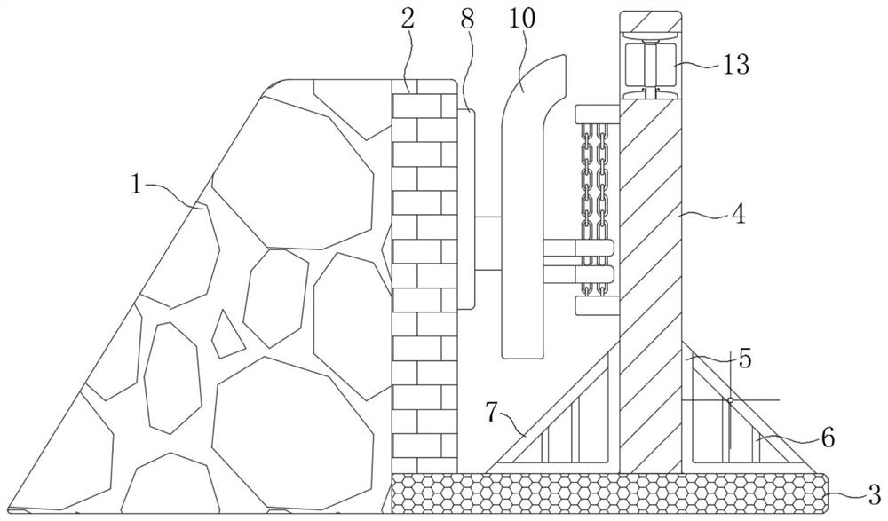
[0037] refer to Figure 1-7 , a vertical water stop structure for water conservancy projects, comprising a subgrade 1, a wall body 2, a base 3 and a blocking plate 10, the base 3 is located at the bottom of the water and connected to the water side of the subgrade 1, and the wall 2 is located on the base 3 and connected to the water side The side wall of the subgrade 1 is attached, and the side wall of the wall 2 opposite to the column 4 is welded with a track 8, and the base 3 is also provided with a column 4 parallel to the wall 2;

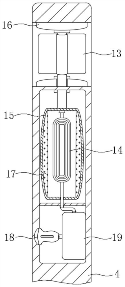
[0038] The top of the column 4 is provided with a water-permeable groove and a runner 13 is installed for rotation. A columnar cavity...


PUM


Abstract

The invention discloses a vertical water-stop structure for water conservancy projects, which comprises a roadbed, a wall body, a base and a blocking plate. The base is located at the bottom of the water and connected to the water side of the roadbed. Rails are welded on the side wall of the body opposite to the column, and the base is also provided with a column; the invention also discloses a construction process of a vertical water-stop structure in a water conservancy project, which includes the following steps: S1: prefabricated concrete slab; S2 : Excavation of foundation pit; S3: Formwork; S4: Binding reinforcement cage; S5: Pouring; S6: Formwork removal; S7: Fixing movable parts. The invention has a novel structure and a simple structure. The blocking plate can automatically rise to a certain height according to the water level. When the water level is higher than the wall, the electric mechanism transmits electric energy through sound waves of a specific frequency, so that the sealing connection between the blocking plate and the track can be quickly realized. Thereby, the height of the vertical waterproof structure is increased, and the purpose of automatic flood prevention without manual operation is realized.

Description

technical field [0001] The invention relates to the technical field of water conservancy engineering, in particular to a vertical water stop structure of a water conservancy project and a construction method thereof. Background technique [0002] With the development of the national economy, the basic construction has gradually improved, and the construction of river related projects closely related to people's lives has also been continuously transformed. River reconstruction is the work of comprehensive river management. According to different requirements, the comprehensive management of the river channel, such as control, dredging, revetment, embankment, etc., can achieve the purpose of safe flood discharge and rational use of water and soil resources. River channel slope protection is an infrastructure in river channel reconstruction. [0003] At present, some vertical concrete structures are used on both sides of the river in some parks and scenic spots to retain water...

Claims


Application Information

Patent Timeline
Patent Type & Authority Patents(China)
IPC IPC(8): E02B3/10
CPCE02B3/104Y02A20/00
Inventor 李清
Owner 宁夏晋明建设工程有限公司
Why Eureka
Try Eureka