
Propylene gas catalytic deoxidation device and method

A gas catalysis and reaction device technology, which is applied in chemical instruments and methods, separation methods, chemical industry, etc., can solve the problems of difficult separation of reducing gas, no catalytic deoxidation technology, and high deoxidation temperature of activated carbon, so as to suppress the by-product CO. The effect of generating, suppressing the occurrence of carbon deposition, and strengthening the bearing capacity

Active Publication Date: 2019-12-13
CHINA PETROLEUM & CHEM CORP +1
View PDF5 Cites 7 Cited by
  • Summary
  • Abstract
  • Description
  • Claims
  • Application Information

AI Technical Summary

Problems solved by technology

[0003] The deoxygenation technologies in the prior art mainly include pressure swing adsorption deoxidation, chemical adsorption deoxidation, activated carbon combustion deoxygenation, and catalytic combustion deoxidation. Among them, physical and chemical adsorption deoxidation has a small load and is suitable for the removal of trace oxygen. high consumption
The catalytic deoxygenation technology in the prior art basically needs to add H 2 and other reducing gases, and the separation of reducing gases has become a more difficult problem to solve
[0004] The organic gas catalytic oxidation deoxygenation technology in the current prior art is mainly aimed at methane-containing gases such as coalbed methane and landfill gas, and the deoxygenation technology for olefins such as ethylene and propylene is only suitable for the removal of trace oxygen at the ppm level, and no one for ethylene Catalytic deoxygenation technology for olefins such as propylene and propylene, but olefins are prone to carbon deposition on the surface of the catalyst at a certain temperature, and its deoxygenation technology is somewhat different from methane deoxygenation technology

Method used


Image

  • Propylene gas catalytic deoxidation device and method

Examples


Embodiment 1

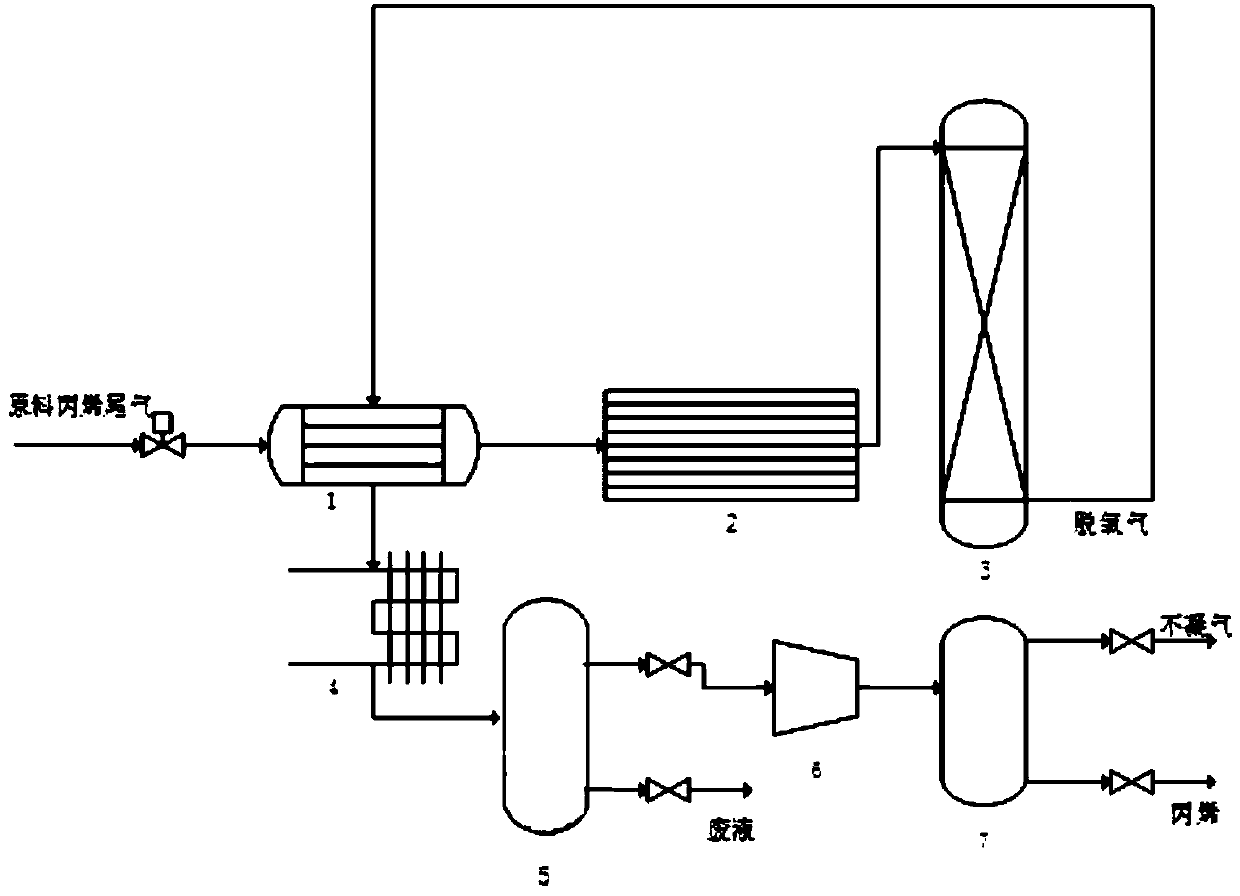
[0040] Composition of propylene tail gas: the concentration of oxygen by volume is 5%, the concentration of propylene by volume is 90%, and the concentration of nitrogen is 5%. Reaction pressure 1MPa, reaction space velocity 10000hr -1. The propylene tail gas is at 40°C. After the heat is exchanged to 120°C by the heat exchanger, it enters the deoxygenation reactor, and the outlet temperature of the reaction bed is 280°C. The gas after the deoxygenation reaction exchanges heat with the raw material gas to 80°C, and after being cooled to 20°C by the air condenser, it enters the gas-liquid separation tank to separate the liquid phase generated during the reaction. Gas phase oxygen content 0.1%, CO selectivity 0.4%, CO 2 99% selectivity. The gas phase enters the non-condensable gas separation tower after being boosted by the compressor, the non-condensable gas is separated from the gas phase, and pure propylene is obtained from the liquid phase. Non-condensable gas compositio...

Embodiment 2

[0042] Composition of propylene tail gas: the concentration of oxygen by volume is 5%, the concentration of propylene by volume is 90%, and the concentration of nitrogen is 5%. Reaction pressure 3MPa, reaction space velocity 50000hr -1 . The propylene tail gas is at 40°C. After the heat is exchanged to 180°C by the heat exchanger, it enters the deoxygenation reactor, and the outlet temperature of the reaction bed is 355°C. The gas after the deoxygenation reaction exchanges heat with the raw material gas to 100°C, and after being cooled to 20°C by the air condenser, it enters the gas-liquid separation tank to separate the liquid phase generated during the reaction. Gas phase oxygen content 0.18%, CO selectivity 0.48%, CO 2 Selectivity 98.05%. The gas phase enters the non-condensable gas separation tower after being boosted by the compressor, the non-condensable gas is separated from the gas phase, and pure propylene is obtained from the liquid phase. Non-condensable gas com...

Embodiment 3

[0044] The composition of the propylene tail gas: the concentration of oxygen by volume is 1%, the concentration of propylene by volume is 96%, and the concentration of nitrogen is 4%. Reaction pressure 2MPa, reaction space velocity 15000hr -1 . The propylene tail gas is at 40°C. After the heat is exchanged to 160°C by the heat exchanger, it enters the deoxygenation reactor, and the outlet temperature of the reaction bed is 210°C. The gas after the deoxygenation reaction exchanges heat with the raw material gas to 60°C, and after being cooled to 20°C by the air condenser, it enters the gas-liquid separation tank to separate the liquid phase generated during the reaction. Gas phase oxygen content 0.08%, CO selectivity 0.02%, CO 2 Selectivity 99.5%. The gas phase enters the non-condensable gas separation tower after being boosted by the compressor, the non-condensable gas is separated from the gas phase, and pure propylene is obtained from the liquid phase. Composition of no...


PUM


Abstract

The invention discloses a propylene gas catalytic deoxidation device and method. The device comprises a heat exchanger, an electric heater, a deoxidation reactor, an air condenser, a gas-liquid separation tank, a compressor and a separation tower; raw propylene tail gas exchanges heat through the heat exchanger, and is further heated to reaction operating temperature through the electric heater, and enters the deoxidation reactor; the deoxidation reactor is internally provided with a catalyst bed, and deoxidized gas enters the gas-liquid separation tank through the air condenser after heat exchange with the raw gas; liquid phases generated in the reaction process are separated, and gas phases enter a non-condensable gas separation tower after being pressurized through the compressor; and non-condensable gas is separated from the gas phases, and pure propylene is obtained from the liquid phases. According to the propylene gas catalytic deoxidation device and method, the propylene directly reacts with oxygen for generating CO2 and H2O; and carbon deposition and generation of byproduct CO on catalyst surfaces can be inhibited, and the device has higher bearing capacity for fluctuationof the oxygen content of the raw gas.

Description

technical field [0001] The invention relates to the technical field of chemical tail gas treatment, in particular to a propylene gas catalytic deoxidation reaction device and a deoxidation method. Background technique [0002] Oxygen-containing organic hydrocarbon gas or tail gas is a common gas in the current chemical production, storage and transportation process, such as organic tail gas in the oxidation and peroxidation process, tail gas from the tank farm communication system, landfill gas, etc., often due to high oxygen content And it brings the risk of explosion; and SH 3009-2013 "Petrochemical Combustible Gas Emission System Design Code" 5.3.1 stipulates that "combustible gases with oxygen content greater than 2% (v%)" should not be discharged into the whole plant Combustible gas discharge systems, such as flares, incinerators, etc. Therefore, in order to reduce the risk of explosion, recycle organic gas or ensure that the oxygen-containing organic tail gas meets th...

Claims


Application Information

Patent Timeline
Patent Type & Authority Applications(China)
IPC IPC(8): C07C7/00C07C11/06B01D53/86B01D53/76B01D53/46B01J19/00
CPCC07C7/005B01D53/8671B01D53/76B01D53/46B01J19/0006B01J19/0013B01D2255/2092B01D2255/30B01D2255/20707B01D2255/50B01D2255/702C07C11/06Y02P20/50
Inventor 姜杰冯俊杰赵磊文松徐伟
Owner CHINA PETROLEUM & CHEM CORP
Learn More