
Stator and rotor punching production line

A production line, stator and rotor technology, applied in the manufacture of stator/rotor bodies, metal processing equipment, manufacturing tools, etc., can solve the problems of low processing efficiency, achieve the effects of improving production and processing efficiency, facilitating subsequent processes, and ensuring smooth cooperation

Active Publication Date: 2021-04-06
苏州艾尔拓机电有限公司
View PDF1 Cites 0 Cited by
  • Summary
  • Abstract
  • Description
  • Claims
  • Application Information

AI Technical Summary

Problems solved by technology

However, in the actual production process, the stator and rotor punches are sequentially loaded, stamped, sorted, and collected. After each process is completed, the workpiece needs to be manually transferred to the next process, and the processing efficiency is low.

Method used


Image

  • Stator and rotor punching production line
  • Stator and rotor punching production line
  • Stator and rotor punching production line

Examples


Embodiment

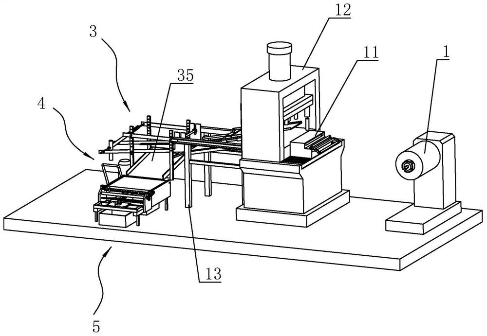
[0042] Embodiment: a kind of stator and rotor stamping production line, such as figure 1 As shown, it includes an uncoiler 1, a yaw feeder 11, a punching machine 12, a base frame 13, a sorting device 3, a first receiving device 4 for collecting stator punches, and a vertically perpendicular to the sorting The device 3 is distributed and used to collect the second receiving device 5 of the rotor punch, and the yaw feeder 11 is installed on the punching machine 12 .

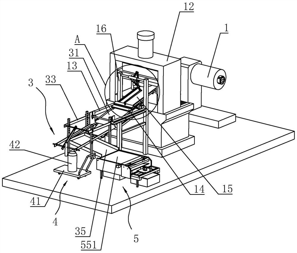
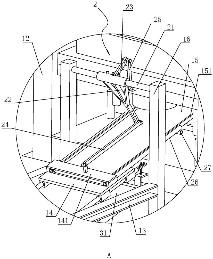
[0043] Such as figure 2 and image 3 As shown, the base frame 13 is fixed on the ground and is located beside the punching machine 12, and the length direction of the base frame 13 is perpendicular to the punching machine 12, and the base frame 13 is provided with a vertical stand 16 near the end of the punching machine 12, standing The frame 16 is provided with a link mechanism 2; the link structure includes a rotating shaft 21 that is rotatably connected in the stand 16, the axis of the rotating shaft 21 is h...


PUM


Abstract

The invention relates to a production line for stator and rotor punching processing, which is applied in the field of processing equipment for stator and rotor punching. The first receiving device for collecting the stator punches and the second receiving device for collecting the rotor punches. The base frame is slidably connected with a sliding seat that moves upwards in the direction close to the stamping die on the punching machine. The sliding seat is equipped with an inclined The material receiving plate, the inclination direction of the material receiving plate is parallel to the moving direction of the sliding seat, the end of the base frame close to the punching machine is provided with a stand, and the connecting rod mechanism is arranged on the stand, and the sliding seat is connected with the punching machine through the connecting rod mechanism. When the first working table of the stamping machine is connected, when the first working table of the punching machine rises, the sliding seat moves upwards obliquely, and when the first working table of the punching machine moves back, the sliding seat moves downwards obliquely; The problem of low processing efficiency has the advantage of improving the processing efficiency of stator and rotor punching.

Description

technical field [0001] The invention relates to the field of processing equipment for stator and rotor punching, in particular to a stator and rotor punching processing production line. Background technique [0002] The structure of the motor is generally composed of a stator, a rotor and other accessories. In the process of making the motor, the silicon steel coil is usually cut into a blanking plate first, and then the blanking plate is punched into circular punches of different sizes, and finally the circular The punching sheet is stamped into shaped stator and rotor punching sheets. [0003] The Chinese patent with the notification number CN207481268U discloses a hydraulic stamping machine, including a support table, a lower stamping die, an upper stamping die, a hydraulic pump, a control panel, an electric push rod and a PLC controller, and an electric push rod is arranged inside the support table , the top of the support table is provided with a lower punching die, th...

Claims


Application Information

Patent Timeline
Patent Type & Authority Patents(China)
IPC IPC(8): H02K15/02B21D22/02B21D43/02B21D43/20
CPCB21D22/02B21D43/027B21D43/20H02K15/02
Inventor 刘腾腾孙红军刘行行
Owner 苏州艾尔拓机电有限公司
Learn More