
Gas detection method and system

A gas detection system and gas detection technology, which is applied in the measurement of color/spectral characteristics, etc., can solve the problems of detection error, different physical environment, large volume of the gas absorption chamber and reference gas chamber, etc., and achieves easy miniaturization, Save system space and facilitate the effect of streamlining

Inactive Publication Date: 2019-12-10
HUAZHONG UNIV OF SCI & TECH +1
View PDF8 Cites 1 Cited by
  • Summary
  • Abstract
  • Description
  • Claims
  • Application Information

AI Technical Summary

Problems solved by technology

[0006] In view of the defects of the prior art, the purpose of the present invention is to solve the problem that the measurement gas absorption gas chamber and the reference gas chamber used in some optical fiber gas absorption detection systems are relatively large in volume, and the physical environments in which the two may be different may cause problems. Detect technical issues that introduce errors

Method used


Image

  • Gas detection method and system
  • Gas detection method and system

Examples


Embodiment Construction

[0038] In order to make the objectives, technical solutions and advantages of the present invention clearer, the present invention will be further described in detail below with reference to the accompanying drawings and embodiments. It should be understood that the specific embodiments described herein are only used to explain the present invention, but not to limit the present invention. In addition, the technical features involved in the various embodiments of the present invention described below can be combined with each other as long as they do not conflict with each other.

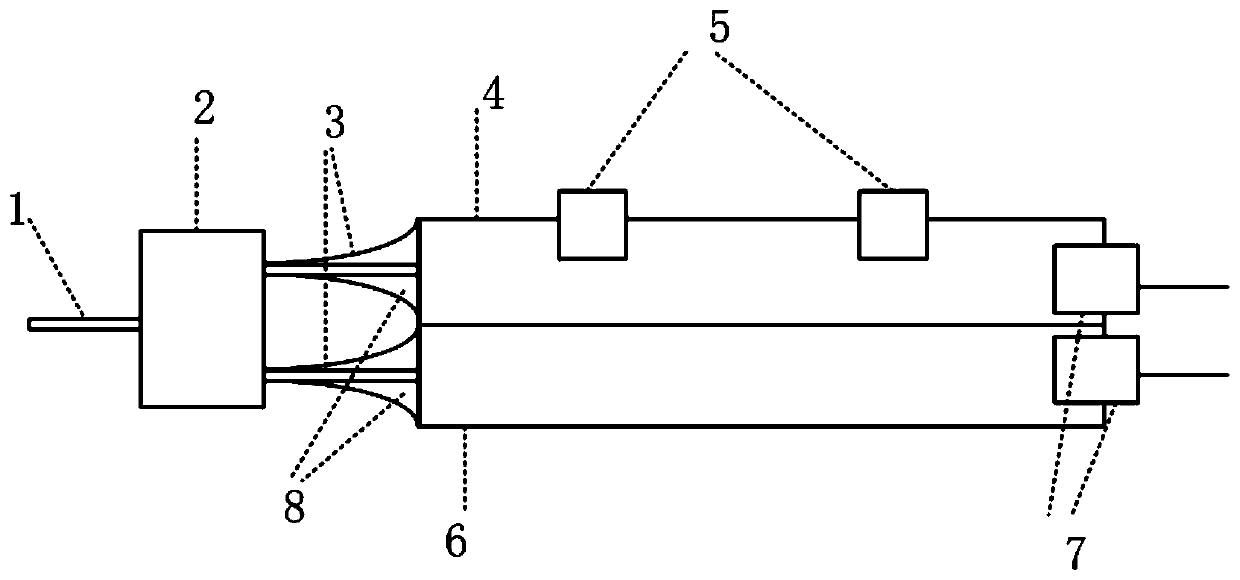
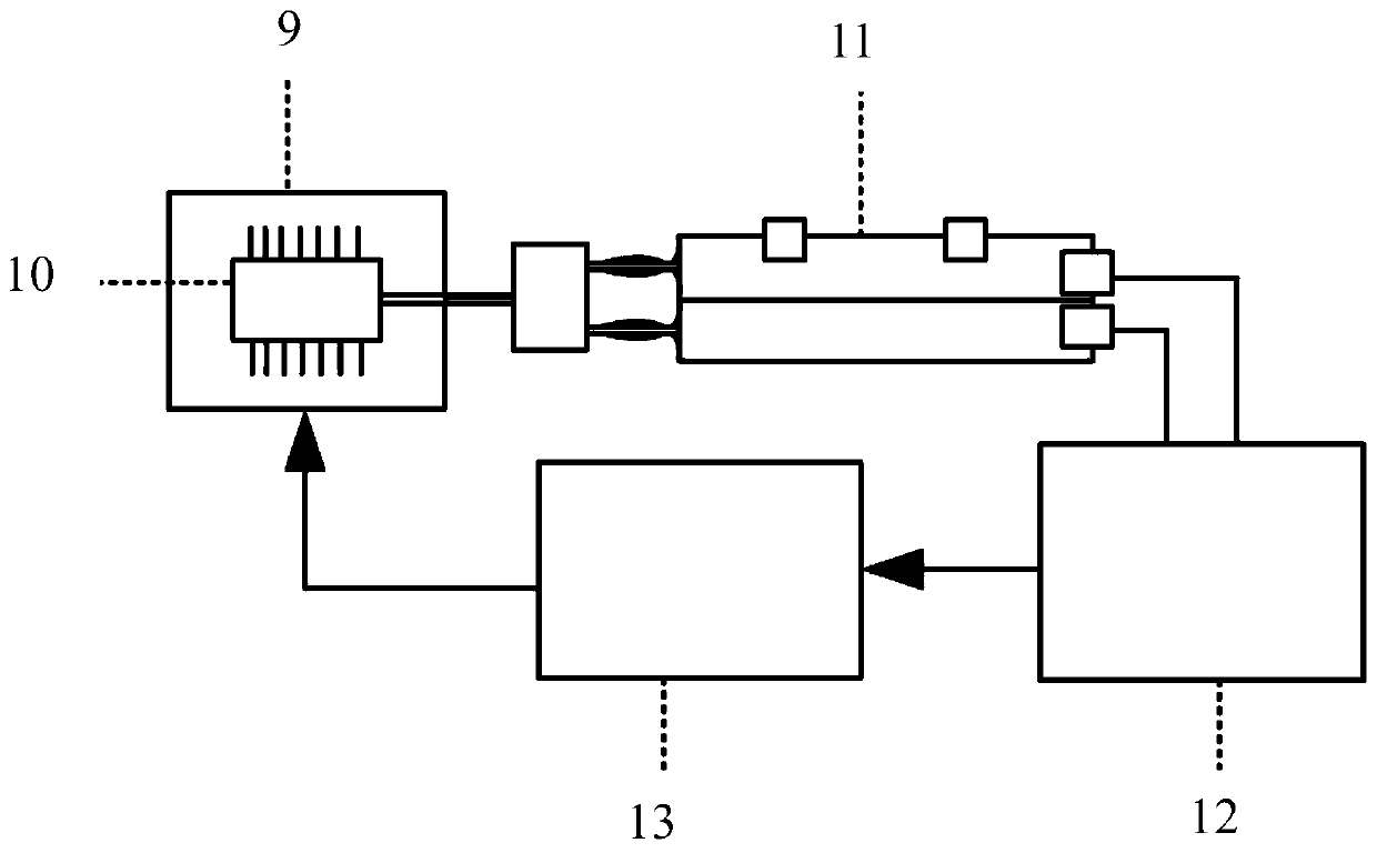
[0039] The invention adopts an embedded optical fiber gas absorption system, integrates the measurement gas absorption gas chamber and the reference gas chamber into the same module, and isolates the reference gas chamber from the measurement gas chamber to ensure the spatial position of the reference gas chamber and the measurement gas chamber In this way, a series of problems caused by the differe...


PUM


Abstract

The invention discloses a gas detection method and system. The gas detection system comprises the following parts that an optical path unit is used for generating two paths of same optical signals; agas chamber unit is divided into a reference gas chamber and a measurement gas chamber which are isolated from each other, wherein reference gas with preset concentration is sealed in the reference gas chamber, and the measurement gas chamber is communicated with the environment where external gas to be measured is located; the two paths of same optical signals respectively enter the reference gaschamber and the measurement gas chamber, the two paths of optical signals are attenuated to different extents after being absorbed by the reference gas chamber and the measurement gas chamber, and the reference gas is the same as the external gas to be measured in type; and a detection unit is used for detecting the two paths of optical signals absorbed by the reference gas chamber and the measurement gas chamber, and determining the concentration of the external gas to be measured according to the intensity of the two paths of optical signals and the concentration of the reference gas. Measurement errors caused by light source optical power jitter and external environment noise are reduced, and the detection precision and sensitivity of the system are improved.

Description

technical field [0001] The present invention relates to the technical field of gas detection, and more particularly, to a gas detection method and system. Background technique [0002] Most of the current fiber optic gas sensors are based on the principle of spectral absorption of gases. According to the different physical quantities detected, it can be divided into two categories: direct spectral absorption and indirect absorption. The direct spectral absorption optical fiber gas sensor uses a light source corresponding to a certain gas absorption line or a certain group of absorption lines to directly detect the change of optical power after gas absorption, thereby obtaining the gas concentration. The principle of the direct spectral absorption fiber optic gas sensor is: the light source emits a beam of light, which is incident into the gas through the optical fiber, a part of the light is absorbed by the gas, and the detector performs photoelectric conversion, and then t...

Claims


Application Information

Patent Timeline
IPC IPC(8): G01N21/31
CPCG01N21/31
Inventor 司马朝坦蔡斌臣袁康蔡一诺高远鲁平刘德明
Owner HUAZHONG UNIV OF SCI & TECH
Learn More