Tension-tension fatigue testing device for fiber rod body and fatigue performance evaluation method

A technology of fatigue testing and evaluation methods, which is applied in the direction of measuring devices, using applied repetitive force/pulsation force to test material strength, strength characteristics, etc., can solve the problem of limiting the application of fiber composite rods, lack of pull-pull fatigue testing, and hinder new materials and the application and development of new structures to achieve the effect of a wide range of applications and a simple structure

Inactive Publication Date: 2019-12-10
HARBIN INST OF TECH
View PDF4 Cites 0 Cited by
  • Summary
  • Abstract
  • Description
  • Claims
  • Application Information

AI Technical Summary

Problems solved by technology

[0006] The present invention aims to solve the lack of research on the pull-pull fatigue test of fiber reinforced composite rods in the prior art, which greatly limits the application of fiber composite rods in bridge stay cables and ground anchors, and hinders The application and development of new materials and new structures in civil engineering, and then provide a tension-tension fatigue test device and fatigue performance evaluation method for fiber rods

Method used


Image

  • Tension-tension fatigue testing device for fiber rod body and fatigue performance evaluation method
  • Tension-tension fatigue testing device for fiber rod body and fatigue performance evaluation method
  • Tension-tension fatigue testing device for fiber rod body and fatigue performance evaluation method

Examples


specific Embodiment approach 1

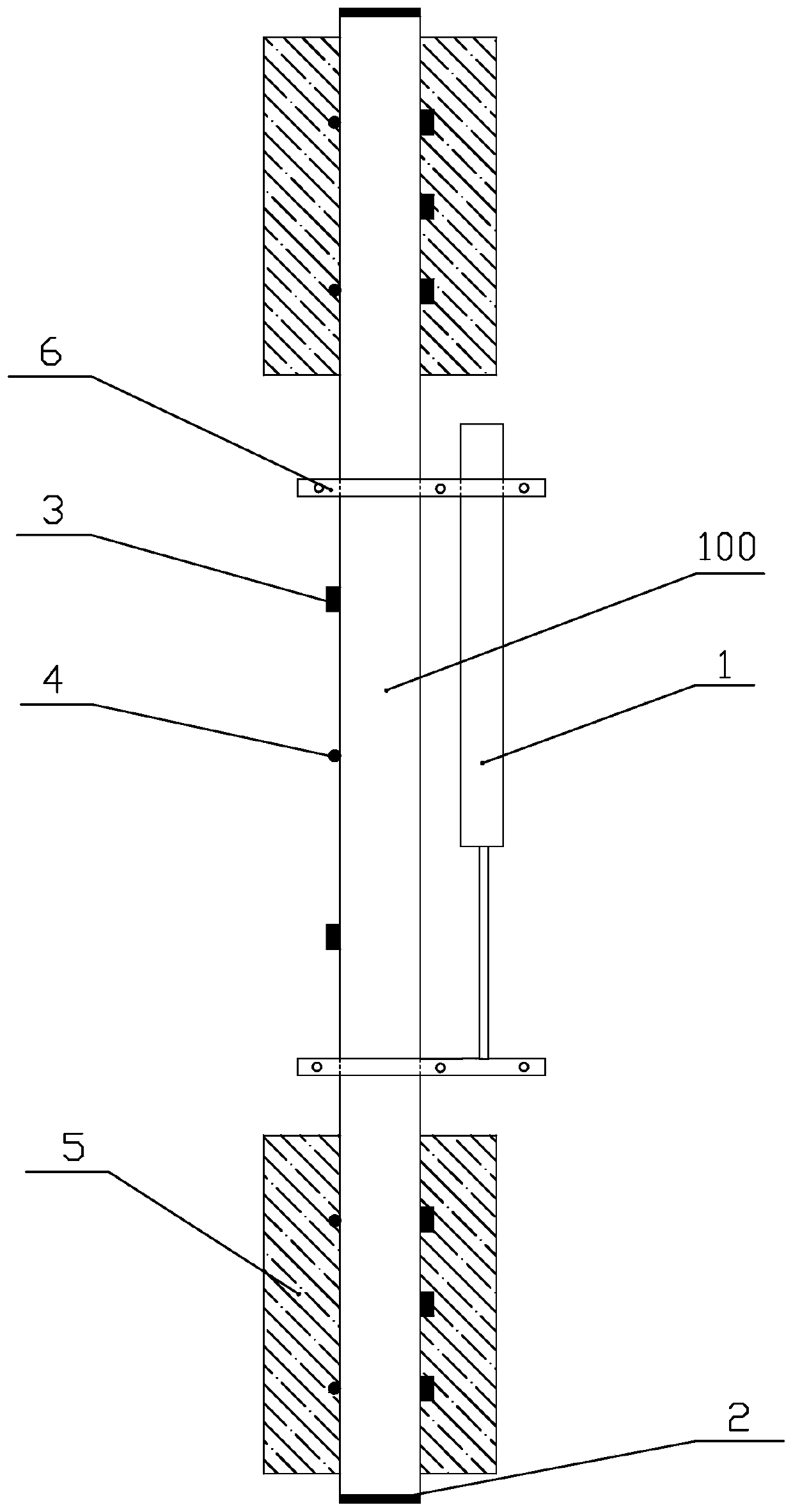
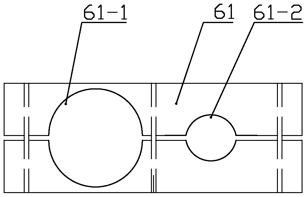
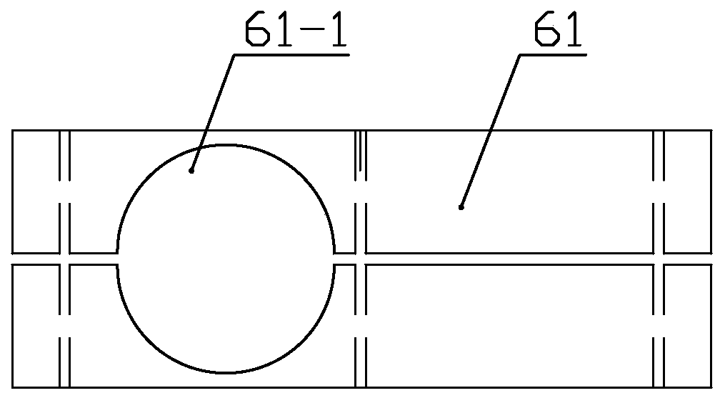
[0033] Specific implementation mode one: combine Figure 1~3 Describe this embodiment, be used for the pull-pull fatigue test device of fiber rod body, it comprises fixing device, displacement sensor 1, piezoelectric sensor 2, strain sensor 3, temperature sensor 4 and anchorage 5, the quantity of described anchorage 5 There are two, the fiber rod body 100 is vertically arranged and its upper and lower parts are respectively anchored by the anchorage 5, the number of the strain sensor 3 and the temperature sensor 4 are several, and are respectively pasted on the surface of the fiber rod body 100, the piezoelectric sensor 2 The quantity is two, and respectively pasted on the two ends of the fiber rod body 100, the displacement sensor 1 is arranged parallel to the fiber rod body 100, and the fixing device includes two positioning plates 6 arranged in parallel up and down, and the two positioning plates 6 Both are fixed on the fiber rod body 100 between the two anchors 5 , the upp...


PUM


Abstract

The invention discloses a tension-tension fatigue testing device for a fiber rod body and a fatigue performance evaluation method, and belongs to the technical field of civil engineering. The problemsthat the application of fiber composite material rod bodies in bridge stay cables, ground anchors and the like is greatly limited and the application and development of new materials and new structures in civil engineering are hindered due to lack of research on the tension-tension fatigue test of the fiber reinforced composite material rod bodies in the prior art are solved. The fiber rod body is vertically arranged, and the upper part and the lower part of the fiber rod body are anchored through anchorage devices respectively. A plurality of strain sensors and a plurality of temperature sensors are bonded to the surface of the fiber rod body; piezoelectric sensors are respectively adhered to two ends of the fiber rod body; and a displacement sensor is parallel to the fiber rod body. A fixing device comprises two positioning plates which are arranged in parallel up and down, the two positioning plates are fixedly arranged on the fiber rod body between the two anchorage devices, and the upper part of the displacement sensor is fixedly connected with the fiber rod body through one positioning plate.

Description

technical field [0001] The invention relates to a tension-tension fatigue test device and a fatigue performance evaluation method for a fiber rod body, belonging to the technical field of civil engineering. Background technique [0002] The life of reinforced concrete structures in civil engineering mainly depends on reasonable design and suitable construction materials. Any defects in these two aspects will lead to early degradation of structural performance. When the traditional reinforced concrete structure has served in the civil engineering environment for a long time, due to the inevitable temperature, humidity, liquid pressure, water (snow), freeze-thaw, acid rain, concrete seepage, river water (sea water) erosion, ultraviolet rays, etc. Aging environment such as irradiation and long-term action of dynamic and static loads will cause the bearing capacity of the reinforced concrete structure to decrease, concrete cracking and steel bar corrosion, etc., which will threa...

Claims


Application Information

Patent Timeline
IPC IPC(8): G01N3/32G01N3/02
CPCG01N3/02G01N3/32G01N2203/0017G01N2203/0073G01N2203/0264G01N2203/0617G01N2203/0623G01N2203/0658G01N2203/0682
Inventor 咸贵军李承高郭瑞董少策
Owner HARBIN INST OF TECH
Why Eureka
Try Eureka