
Photoacoustic imaging system and imaging method thereof

A photoacoustic imaging and laser technology, applied in the field of medical devices, can solve the problems of low sensitivity, small imaging depth of imaging system, imaging, etc., to achieve the effect of increasing laser pulse energy, realizing frame rate imaging, and increasing repetition frequency

Pending Publication Date: 2019-12-10
INNERMEDICAL CO LTD
View PDF3 Cites 3 Cited by
  • Summary
  • Abstract
  • Description
  • Claims
  • Application Information

AI Technical Summary

Problems solved by technology

[0003] However, under the current technical conditions, pulsed lasers used for photoacoustic imaging cannot meet the requirements of high repetition rate and high pulse energy output at the same time.
Existing pulsed lasers on the market only have two types: high repetition rate but low pulse energy and low repetition frequency but high pulse energy. Lasers with low energy will cause the imaging depth of the entire imaging system to be too small and the sensitivity to be too low

Method used


Image

  • Photoacoustic imaging system and imaging method thereof

Examples


Embodiment 1

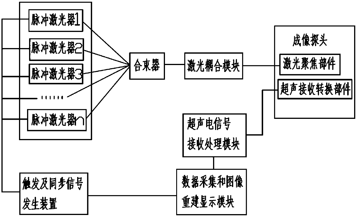
[0024] Such as figure 1 As shown, the pulsed lasers 1~n are lasers with high repetition rate but low pulse energy. The n beams of laser light emitted by it are merged into a high-energy pulsed laser beam through the beam combiner, and enter the laser beam through the laser coupling module. Focus widget. The imaging method of the photoacoustic imaging system is as follows:

[0025] Under the triggering of the trigger and synchronization signal generator, n lasers simultaneously emit n beams of low pulse energy lasers, which are combined into a beam of high-energy laser pulses, which are focused by the laser focusing part in the imaging probe and then irradiated to biological tissues to excite biological tissues. An ultrasonic signal is emitted. The ultrasonic signal is received by the ultrasonic receiving and converting part in the imaging probe, converted into an electrical signal and sent to the ultrasonic electrical signal receiving and processing module. Under the synchr...

Embodiment 2

[0027] Such as figure 1 As shown, the pulsed lasers 1~n are lasers with low repetition rate but high pulse energy. They sequentially emit n beams of laser light within the light emitting period interval of a single laser, enter the laser coupling module through the beam combiner, and finally reach the laser focusing component. The imaging method of the photoacoustic imaging system is as follows:

[0028] Triggered by the trigger and synchronization signal generator, n lasers sequentially emit n beams of high-pulse energy lasers within the light-emitting cycle interval of a single laser, and irradiate the biological tissue after being focused by the laser focusing part in the imaging probe to excite the biological tissue An ultrasonic signal is emitted. The ultrasonic signal is received by the ultrasonic receiving and converting part in the imaging probe, converted into an electrical signal and sent to the ultrasonic electrical signal receiving and processing module. Under th...


PUM


Abstract

The invention provides a photoacoustic imaging system and an imaging method thereof. The photoacoustic imaging system comprises n pulsed lasers, a beam combiner and a triggering and synchronizing signal generating device, wherein n is greater than or equal to 2; the signal control ends of the pulsed lasers are connected with the triggering and synchronizing signal generating device; laser beams emitted by the n pulsed lasers are combined into one beam through the beam combiner, and then the beam is transmitted; the beam combiner is connected with a laser coupling module; the laser coupling module is connected with a laser focusing component; an ultrasonic receiving and converting component is connected with an ultrasonic electrical signal receiving and processing module; the ultrasonic electrical signal receiving and processing module is connected with a data collecting and image reconstructing display module; and the data collecting and image reconstructing display module is connectedwith the triggering and synchronizing signal generating device. Through the adoption of the technical scheme of the photoacoustic imaging system disclosed by the invention, the whole photoacoustic imaging system can meet double requirements of obtaining high imaging frame rate and enough imaging depth on biologic tissue.

Description

technical field [0001] The invention belongs to the technical field of medical devices, and in particular relates to a photoacoustic imaging system and an imaging method thereof. Background technique [0002] Photoacoustic imaging is a non-destructive medical imaging method developed in recent years, which can provide high-resolution and high-contrast tissue imaging. Photoacoustic imaging is a non-destructive biophoton imaging method based on the difference in optical absorption inside biological tissues and using ultrasound as a medium. It combines the advantages of high contrast characteristics of pure optical imaging and high penetration depth characteristics of pure ultrasound imaging. The detection of photoacoustic waves replaces the photon detection in optical imaging, avoids the influence of optical scattering in principle, and can provide high-contrast and high-resolution tissue images. Features provide important means, and have broad application prospects in the fi...

Claims


Application Information

Patent Timeline
IPC IPC(8): A61B5/00
CPCA61B5/0033A61B5/0095
Inventor 赵心涛黄赞力
Owner INNERMEDICAL CO LTD
Learn More