A method and apparatus in wireless communication
A wireless signal and signaling technology, which is applied in the field of low-latency transmission based on long-term evolution, and can solve the problem of inability to obtain frequency diversity gain.
- Summary
- Abstract
- Description
- Claims
- Application Information
AI Technical Summary
Problems solved by technology
Method used
Image
Examples
Embodiment 1
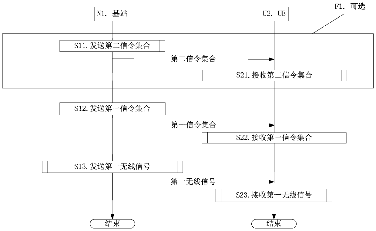
[0170] Embodiment 1 illustrates the flow chart of downlink transmission, as attached figure 1 shown. attached figure 1 In , base station N1 is the maintenance base station of the serving cell of UE U2, and the steps identified in block F1 are optional.
[0171] for base station N1 , the second signaling set is sent in step S11, the first signaling set is sent in step S12, and the first wireless signal is sent in step S13.
[0172] for UE U2 , the second signaling set is received in step S21, the first signaling set is received in step S22, and the first wireless signal is received in step S23.
[0173] In Embodiment 1, the time-domain resource occupied by the first wireless signal belongs to a target time interval, and the target time interval is one of L time intervals, where L is a positive integer greater than 1, and the L The duration of any one of the intervals is less than 1 millisecond. The first wireless signal carries a first bit block, the first bit block inclu...
Embodiment 2
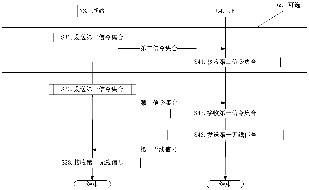
[0181] Embodiment 2 illustrates the flow chart of uplink transmission, as attached figure 2 shown. attached figure 2 In , base station N3 is the maintenance base station of the serving cell of UE U4, and the steps identified in block F2 are optional.
[0182] for base station N3 , the second signaling set is sent in step S31, the first signaling set is sent in step S32, and the first wireless signal is received in step S33.
[0183] for UE U4 , the second signaling set is received in step S41; the first signaling set is received in step S42, and the first wireless signal is sent in step S43.
[0184] In Embodiment 2, the time-domain resource occupied by the first wireless signal belongs to a target time interval, and the target time interval is one of L time intervals, where L is a positive integer greater than 1, and the L The duration of any one of the intervals is less than 1 millisecond. The first wireless signal carries a first bit block, the first bit block inc...
Embodiment 3
[0192] Embodiment 3 illustrates a schematic diagram of the relationship between the target time interval and L time intervals, as attached image 3 shown. in the attached image 3 , each box represents one of the L time intervals, the filled boxes represent the target time interval, the target time interval is one of the L time intervals, and the L time intervals form a A subframe (subframe), the L is a positive integer greater than 1.
[0193] In sub-embodiment 1 of embodiment 3, any one of the L time intervals includes R consecutive OFDM symbols in the time domain, the OFDM symbols include a cyclic prefix, and R is a positive integer.
[0194] In sub-embodiment 2 of embodiment 3, the durations of the L time intervals are the same.
[0195] In sub-embodiment 3 of embodiment 3, the durations of two time intervals among the L time intervals are different.
PUM
 Abstract
Description
Claims
Application Information
 - Generate Ideas
- Intellectual Property
- Life Sciences
- Materials
- Tech Scout
- Unparalleled Data Quality
- Higher Quality Content
- 60% Fewer Hallucinations
Browse by: Latest US Patents, China's latest patents, Technical Efficacy Thesaurus, Application Domain, Technology Topic, Popular Technical Reports.
© 2025 PatSnap. All rights reserved.Legal|Privacy policy|Modern Slavery Act Transparency Statement|Sitemap|About US| Contact US: help@patsnap.com


