
Passive cross-season energy supply and energy storage system

A passive, cross-seasonal technology, applied in the field of cross-seasonal energy storage, can solve the problems of unfavorable BTES heat storage/heat extraction process fine management, different drilling thermal diffusivity and heat transfer efficiency, and BTES usable capacity deviation from the design value, etc. , to achieve the effect of reducing construction complexity and required construction period, reducing ecological impact, and eliminating filler backfilling steps

Pending Publication Date: 2019-12-06
ANHUI UNIVERSITY OF ARCHITECTURE
View PDF7 Cites 1 Cited by
  • Summary
  • Abstract
  • Description
  • Claims
  • Application Information

AI Technical Summary

Problems solved by technology

For example, the double U tube / special-shaped tube is prone to deformation during the drilling process, causing the double U tube / special-shaped tube to fit together (commonly known as "short circuit"), causing part or even all of the buried pipe below the short-circuit point to fail, making the entire The actual usable capacity of BTES seriously deviates from the design value
In addition, the filler backfilling process may also produce uneven backfilling due to different drilling conditions and random backfilling operations, resulting in differences in thermal diffusivity and heat transfer efficiency of drilled holes at different positions, which is not conducive to the BTES heat storage / heat extraction process. Fine management

Method used


Image

  • Passive cross-season energy supply and energy storage system
  • Passive cross-season energy supply and energy storage system
  • Passive cross-season energy supply and energy storage system

Examples


Embodiment Construction

[0031] The present invention will be described in detail below in conjunction with the accompanying drawings and specific embodiments.

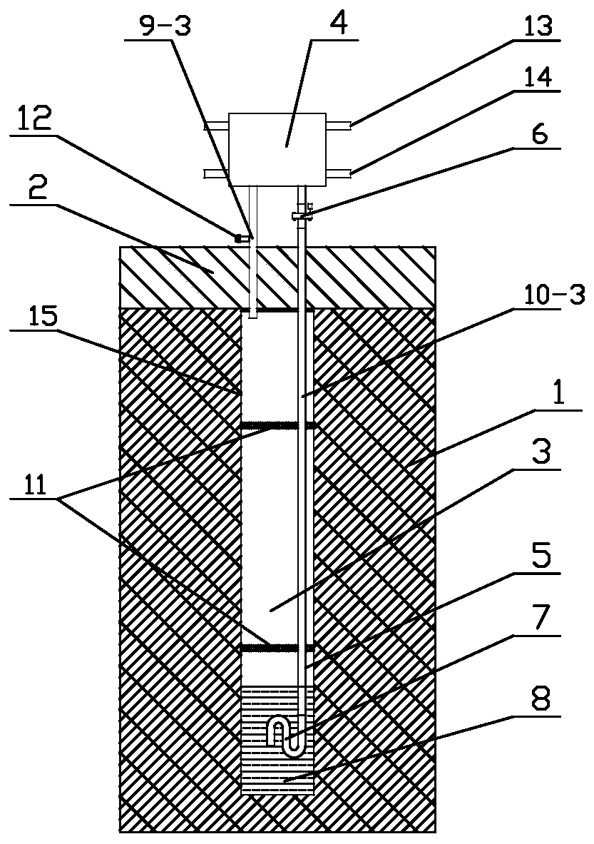
[0032] The structural schematic diagram of the passive cross-seasonal energy storage system of the present invention is as follows: figure 1 As shown in, it includes a sealed container 3 for filling phase change working medium 8 and buried in an energy storage body, a heat exchanger 4, a first fluid pipe 9-3 and a second fluid pipe 10-3, the first fluid pipe 9-3 and the second fluid pipe 10-3. One end of a fluid pipe 9 - 3 communicates with the first working fluid interface of the heat exchanger 4 , the other end passes through the upper end of the sealed container 3 and the end surface of the nozzle is located at the inner upper part of the sealed container 3 . One end of the second fluid pipe 10 - 3 communicates with the second working medium interface of the heat exchanger 4 , the other end passes through the upper end of the sealed contai...


PUM


Abstract

The invention discloses a passive cross-season energy supply and energy storage system which aims to provide a system capable of realizing integrated switching of energy storage and energy supply of the same system by using a passive latent heat heat-exchange manner. The passive cross-season energy supply and energy storage system comprises a sealed container where a phase change working medium isfilled and which is buried in an energy storage body, a heat exchanger, a first fluid pipe and a second fluid pipe, wherein one end of the first fluid pipe is in communication with a first working medium port of the heat exchanger, the other end of the first fluid pipe passes through the upper end face of the sealed container, and the end face of a pipe opening is located at the upper portion inside the sealed container; one end of the second fluid pipe communicates with a second working medium port of the heat exchanger, the other end of the second fluid pipe passes through the upper end face of the sealed container, and the lower end face of the pipe opening is immersed into a phase change working medium; a liquid absorption control unit is installed on the second fluid pipe; and liquidabsorption cores are arranged in the positions, on the two sides of the liquid absorption control unit, in the second fluid pipe. The system adopts the passive latent heat heat-exchange manner, the transmission power consumption of the system can be greatly reduced, the heat exchange capacity per unit meter is effectively increased, and the system runs stably.

Description

technical field [0001] The invention relates to the technical field of cross-seasonal energy storage, and more specifically, relates to a passive system for heating in winter, a passive system for cooling in summer, a passive cross-seasonal energy storage system and an operation control method thereof. Background technique [0002] Among the interseasonal energy storage technologies, interseasonal buried tube energy storage (BTES) has unique application advantages and potentials due to its high coupling with the heat pump system. As we all know, BTES contains a large number of components such as boreholes, fillers, borehole heat exchangers, circulating fluids, manifolds and water pumps. The traditional BTES mainly injects / extracts heat into the ground by driving the circulating fluid (water) through the buried pipe through the water pump. It belongs to the active sensible heat exchange system. Thermal efficiency is also lower. Therefore, engineering designers have to incre...

Claims


Application Information

Patent Timeline
Patent Type & Authority Applications(China)
IPC IPC(8): F28D20/02F28F27/00
CPCF28D20/021F28F27/00Y02E60/14
Inventor 陈萨如拉杨洋
Owner ANHUI UNIVERSITY OF ARCHITECTURE
Learn More