
Discharge current testing circuit of pulse capacitor, testing device and testing way

A pulse capacitor and discharge current technology, applied in the direction of measuring devices, voltage/current isolation, measuring current/voltage, etc., can solve problems such as inconsistent test results, easy to generate arcs, large pulse currents, etc., to achieve simple loops and accurate testing , the effect of accurate test results

Pending Publication Date: 2019-12-03
FUJIAN TORCH ELECTRON TECH CO LTD
View PDF0 Cites 2 Cited by
  • Summary
  • Abstract
  • Description
  • Claims
  • Application Information

AI Technical Summary

Problems solved by technology

[0002] A capacitor is a component that can store charges, and it is also one of the most commonly used electronic components. Compared with ordinary capacitors, pulse capacitors can store the charging energy of a small power supply for a long time interval, and when needed, quickly The energy in a short time interval is released to form a strong impact current and a strong impact power. Capacitors are commonly used electrical components. In order to ensure that accurate capacitors can be selected during use, the discharge performance of the capacitor must be tested. Capacitors can instantly form a strong inrush current. The existing detection capacitor discharge circuit is usually used to detect ordinary capacitors, that is, a discharge switch is used to directly control the discharge and charge of the capacitor, but because the pulse current generated by the pulse capacitor is large and the time is short , can release more than 3000A current in a microsecond instant, direct control with the discharge switch is easy to generate arcs, which will cause serious discrepancies in test results

Method used


Image

  • Discharge current testing circuit of pulse capacitor, testing device and testing way

Examples


Embodiment Construction

[0023] The present invention will be further described below through specific embodiments.

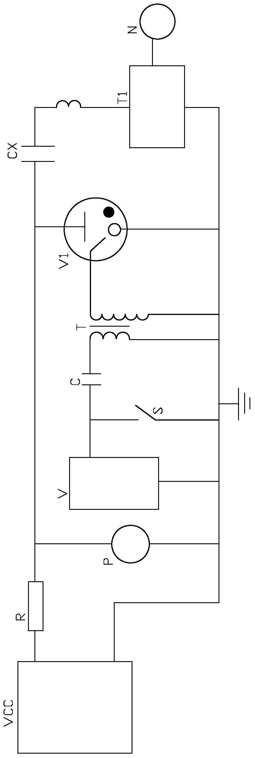
[0024] refer to figure 1 , the present invention provides a pulse capacitor discharge current test device, including a housing and a test circuit, the test circuit includes a detection circuit and a trigger circuit, the detection circuit includes a capacitor under test CX, a power supply VCC for powering the capacitor under test, a series connection A resistor R with a resistance value of 1-5MΩ between the measured capacitor CX and the power supply VCC, a voltmeter P connected in parallel with the power supply VCC, and a trigger tube V1 connected in parallel with the measured capacitor CX are used to collect the measured capacitor A current transformer T1 for CX discharge current and a current display device N connected to the current transformer T1 for displaying current.

[0025] The trigger circuit is connected to the trigger tube V1, and the trigger circuit is used to control the ...


PUM


Abstract

The invention provides a discharge current testing circuit of a pulse capacitor, a testing device and a testing way. The testing circuit comprises a detection loop and a trigger loop; the detection loop comprises a power supply source for supplying power for a tested capacitor, a trigger tube in parallel connection with the tested capacitor, a current transformer for collecting the discharge current of the tested capacitor, and a current display device connected with the current transformer and used for displaying the current; the trigger loop is connected with the trigger tube, the trigger loop is used for controlling the on-off of the trigger tube, thereby controlling the charging and discharging of the tested capacitor. The charging and discharging of the tested capacitor are controlledby arranging the trigger loop, the current transformer is used for collecting the sensing current, thereby preventing the arc phenomenon from occurring to influence the testing precision; the testingresult is more accurate; and the charging time of the tested capacitor and the number of charging and discharging can be set and monitored by arranging the control panel; the testing circuit is safeand stable, the testing is accurate, and the loop is simple.

Description

technical field [0001] The invention relates to the technical field of capacitor detection, in particular to a pulse capacitor discharge current test circuit, a test device and a test method. Background technique [0002] A capacitor is a component that can store charges, and it is also one of the most commonly used electronic components. Compared with ordinary capacitors, pulse capacitors can store the charging energy of a small power supply for a long time interval, and when needed, quickly The energy in a short time interval is released to form a strong impact current and a strong impact power. Capacitors are commonly used electrical components. In order to ensure that accurate capacitors can be selected during use, the discharge performance of the capacitor must be tested. Capacitors can instantly form a strong inrush current. The existing detection capacitor discharge circuit is usually used to detect ordinary capacitors, that is, a discharge switch is used to directly ...

Claims


Application Information

Patent Timeline
Patent Type & Authority Applications(China)
IPC IPC(8): G01R31/00G01R15/18G01R19/00
CPCG01R31/00G01R15/183G01R19/0092
Inventor 吴文辉黄晓云王凯星张子山
Owner FUJIAN TORCH ELECTRON TECH CO LTD
Learn More