
Novel pre-buried unit type ultra-long life multi-directional deflection bridge telescopic device

A super long-life, multi-directional displacement technology, applied in the field of bridge expansion joints, can solve the problems of uneven tooth plate, easy to cause traffic accidents, warping, etc., to strengthen the firmness and strength, shorten the installation period, and increase the number of welding parts. Effect

Pending Publication Date: 2019-12-03
天津桥通科技发展有限公司 +1
View PDF0 Cites 1 Cited by
  • Summary
  • Abstract
  • Description
  • Claims
  • Application Information

AI Technical Summary

Problems solved by technology

[0003] At present, the expansion joints produced in the same field have the following disadvantages: 1. It is difficult to install. The construction can only start after the pavement is completed. Before installation, it needs to be grooved, and the garbage and the garbage and asphalt blocks falling in the middle joint can be removed before the joint can be installed. Installation, and then pouring concrete and other processes, the process is very cumbersome, consumes a lot of time and manpower, and garbage will cause environmental pollution
2. It is fixed and supported by bolts, shear nails, etc. Under the action of shear force, corrosion and oxidation, it will be loose and sheared, resulting in loosening and warping of the tooth plate, which can easily cause traffic accidents
At this time, if it is repaired, the maintenance process needs to excavate concrete and other processes, which is very cumbersome, and the long-term maintenance process will also cause inconvenience to traffic.
3. The installation must be carried out in strict accordance with the specified installation size. A slight negligence will cause the tooth plate to be uneven, and the second adjustment will be required. In more serious cases, the installed comb plate will even need to be dismantled and remade.

Method used


Image

  • Novel pre-buried unit type ultra-long life multi-directional deflection bridge telescopic device
  • Novel pre-buried unit type ultra-long life multi-directional deflection bridge telescopic device

Examples


Embodiment Construction

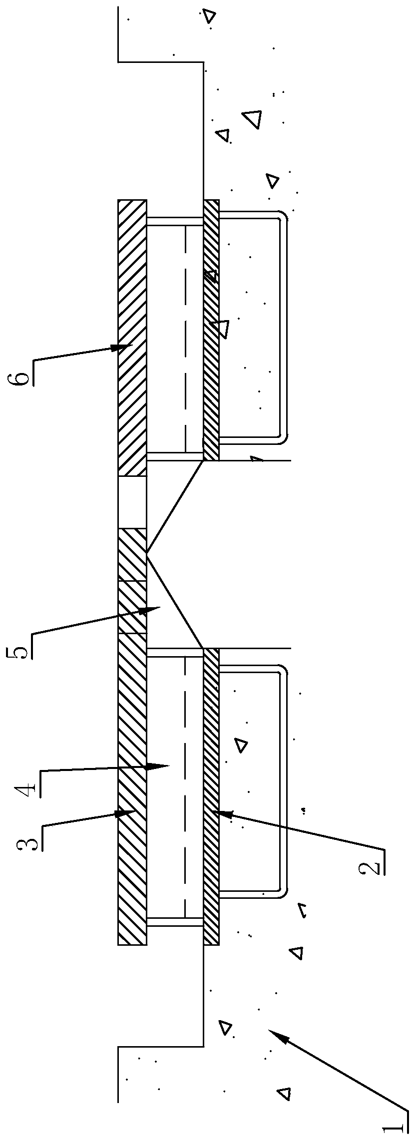
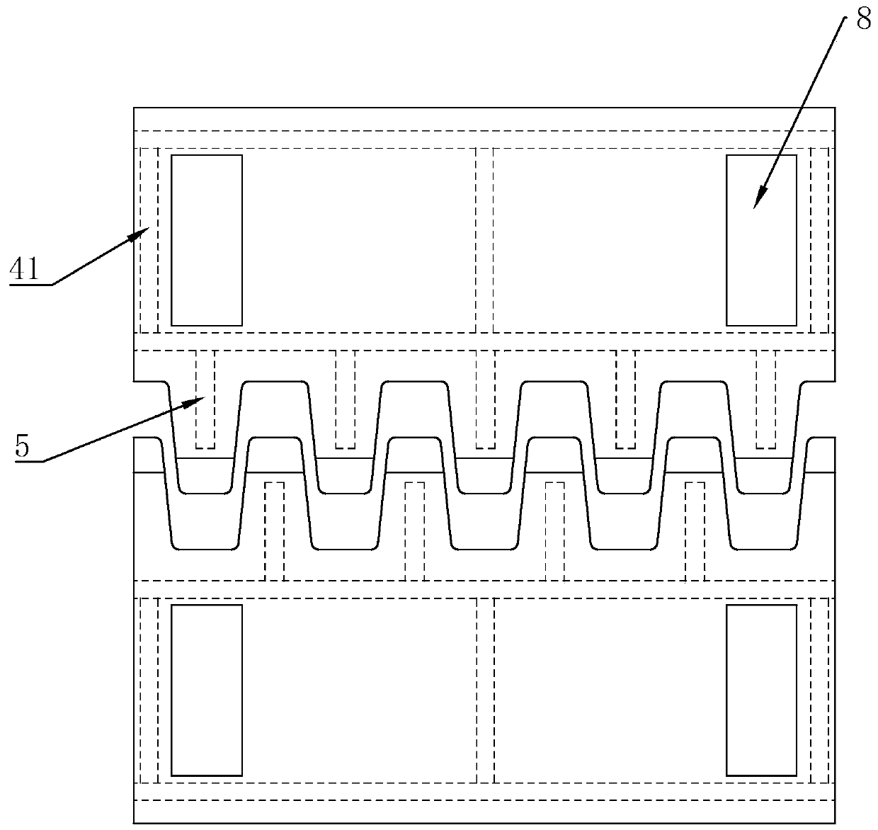
[0020] Such as Figure 1-Figure 2 As shown, the present invention provides a new pre-embedded unit type ultra-long life multi-directional displacement bridge telescopic device, including a main tooth plate 3 and an auxiliary tooth plate 6, and the main tooth plate 3 is installed on the first bridge girder body 1, The auxiliary tooth plate 6 is installed on the second bridge beam body 7, the comb teeth of the main tooth plate 3 and the auxiliary tooth plate 6 cross each other and have gaps, and are located between the first bridge beam body 1 and the second bridge beam body 7 Above the gap, steel plates 2 are preset between the main tooth plate 3 and the first bridge beam body 1, and between the auxiliary tooth plate 6 and the second bridge beam body 7, and the steel plates 2 are respectively connected to the first bridge beam body through the anchor ring 1. The second bridge beam body 7 is fixed, and the lower part of the main tooth plate 3 and the auxiliary tooth plate 6 are ...


PUM


Abstract

The invention relates to a novel pre-buried unit type ultra-long life multi-directional deflection bridge telescopic device. The novel pre-buried unit type ultra-long life multi-directional deflectionbridge telescopic device comprises a main toothed plate and an auxiliary toothed plate; steel plates are preinstalled between the main toothed plate and a first bridge beam body as well as between the auxiliary toothed plate and a second bridge beam body; the steel plates are fixed to the first bridge beam body and the second bridge beam body through anchor rings; box bodies are fixed to the lower portions of toothed plate parts of the main toothed plate and the auxiliary toothed plate correspondingly, and the box bodies are fixed to the steel plates; first stiffening plates are fixed to thelower portions of comb tooth parts of the main toothed plate and the auxiliary toothed plate, the side surfaces of the first stiffening plates are fixed to the box bodies, the interior of each box body is of a cavity structure, and concrete is poured in the cavity structures; and the toothed plate parts of the main toothed plate and the auxiliary toothed plate are provided with a plurality of welding holes at equal intervals in the transverse direction of the toothed plate parts, and the welding holes communicate with the interiors of the box bodies. The novel pre-buried unit type ultra-long life multi-directional deflection bridge telescopic device is high in structural strength, and capable of achieving quick installing and saving construction time.

Description

technical field [0001] The invention relates to the technical field of bridge expansion joints, in particular to a novel pre-embedded unit type ultra-long-life multi-directional displacement bridge expansion device. Background technique [0002] In order to meet the needs of bridge girder deformation, bridge expansion joints are generally installed between the two girder ends of the bridge, between the girder end and the abutment, or at the hinge position of the bridge. With the development of road transportation, road traffic volume and The load of automobiles is getting bigger and bigger, and the performance requirements for the expansion and contraction of highway bridges are constantly improving. [0003] At present, the expansion joints produced in the same field have the following disadvantages: 1. It is difficult to install. The construction can only start after the pavement is completed. Before installation, it needs to be grooved, and the garbage and the garbage and...

Claims


Application Information

Patent Timeline
IPC IPC(8): E01D19/06
CPCE01D19/06E01D19/065
Inventor 田欣孙莉
Owner 天津桥通科技发展有限公司
Learn More