
Tunable filter

A filter and tuning screw technology, applied in waveguide-type devices, electrical components, circuits, etc., can solve the problems of bulky system, difficult production, insufficient stability, etc., achieve compact structure, and increase the effect of out-of-band suppression

Pending Publication Date: 2019-11-29
PIVOTONE COMM TECH
View PDF2 Cites 0 Cited by
  • Summary
  • Abstract
  • Description
  • Claims
  • Application Information

AI Technical Summary

Problems solved by technology

2 Huawei's tunable filter (WO2016095165A1) uses screw debugging to realize the tunable filter. At that time, the screw method itself had problems such as insufficient stability, electromagnetic leakage, and production difficulties.
For the point-to-point communication system in the 6G or 7 / 8GHz frequency band, if the above method is still used, the size of the adjustable filter / duplexer will be too large, resulting in the system being too bulky

Method used


Image

  • Tunable filter
  • Tunable filter
  • Tunable filter

Examples


Embodiment Construction

[0029] In order to make the purpose and technical solutions of the embodiments of the present invention more clear, the technical solutions of the embodiments of the present invention will be clearly and completely described below in conjunction with the drawings of the embodiments of the present invention. Apparently, the described embodiments are some, not all, embodiments of the present invention. Based on the described embodiments of the present invention, all other embodiments obtained by persons of ordinary skill in the art without creative efforts shall fall within the protection scope of the present invention.

[0030] Those skilled in the art can understand that, unless otherwise defined, all terms (including technical and scientific terms) used herein have the same meaning as commonly understood by one of ordinary skill in the art to which this invention belongs. It should also be understood that terms such as those defined in commonly used dictionaries should be und...


PUM


Abstract

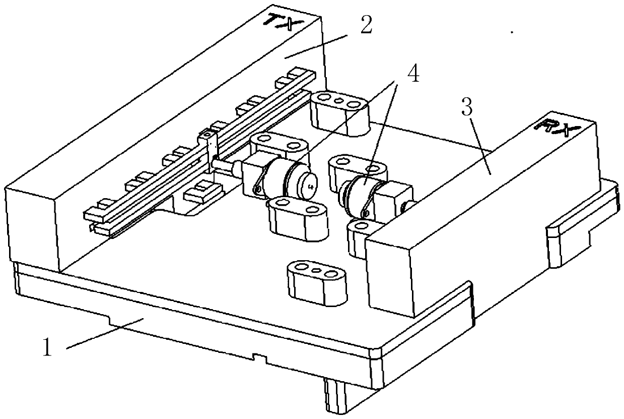
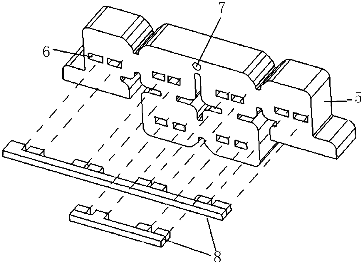
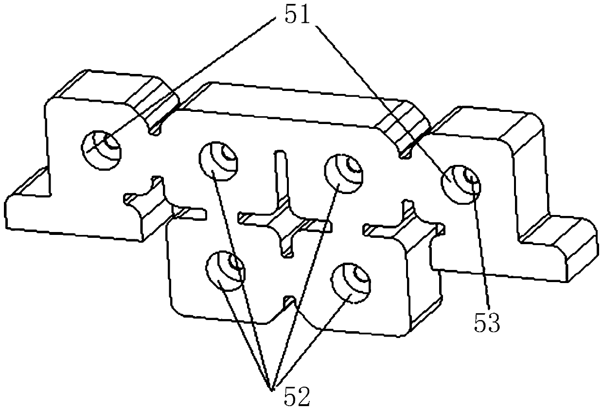
The invention relates to a tunable filter, which is characterized in that each cavity of the filter is internally provided with a resonant column to form a structure close to a coaxial resonant cavity, the side wall of the quasi-coaxial structure is provided with at least two gaps which surround the resonant column and are arranged in the axial direction, a dielectric sheet extends into the resonant cavity through the gaps to realize the adjustment of the passband frequency range of the tunable filter. The tunable filter is suitable for the lower frequency band of microwave point-to-point communication, and the volume of the filter can be reduced through the loading of the resonant columns and the quasi-coaxial cavity loading technology. The band cross coupling is realized by a double-layer dielectric sheet structure which is matched with the cavity arrangement. In the whole tuning range of the tunable filter, the distance between a transmission zero point realized by cross coupling and a passband can be basically kept unchanged, the passband width of the filter can be basically kept unchanged, and the echo of the filter can be kept at a relatively good level at the same time. Thetransmission zero point is realized by adopting cross coupling, and the out-of-band rejection degree of the filter can be greatly increased.

Description

technical field [0001] The invention relates to the field of adjustable microwave devices, in particular to an adjustable filter. Background technique [0002] In recent years, due to the needs of the development of communication systems, tunable filters in the microwave frequency band have a wide range of needs. Such as Huawei, ZTE, NEC, Ericsson, etc. have carried out in-depth research in this field. Among them, NEC started research in this area as early as 2005, and published relevant research results in 2010. [0003] At present, the methods used in the microwave field mainly include the following: 1. The medium rotation method proposed by NEC Corporation of Japan to realize the tunable filter (patent number: WO2010150815A1), using a piece of high dielectric constant medium as the tuning mechanism, through the stepping motor Drive a shaft to rotate and turn the medium sheet to tune, so as to achieve an adjustable effect. 2 Huawei's tunable filter (WO2016095165A1) uses...

Claims


Application Information

Patent Timeline
Patent Type & Authority Applications(China)
IPC IPC(8): H01P1/208
CPCH01P1/208
Inventor 江顺喜彭海璐张丽玲项显梁国春殷实周方平朱文举
Owner PIVOTONE COMM TECH
Learn More