
A maintenance system for gear flaw detection

A flaw detection and gear technology, applied in measuring devices, using sonic/ultrasonic/infrasonic waves to analyze solids, and using sonic/ultrasonic/infrasonic waves for material analysis, etc. Wide range of use, improved effect, guaranteed perfect meshing effect

Active Publication Date: 2022-07-01
BEIJING MAGNETIC FLUX EQUIP MFG
View PDF4 Cites 0 Cited by
  • Summary
  • Abstract
  • Description
  • Claims
  • Application Information

AI Technical Summary

Problems solved by technology

[0004] The traditional gear flaw detection device can only meet the flaw detection operation of the gear under static conditions, and cannot perform continuous flaw detection on the running gear, which is not conducive to the detection and observation of the internal structure and damage of the gear in the running state, thus affecting the detection effect

Method used


Image

  • A maintenance system for gear flaw detection
  • A maintenance system for gear flaw detection
  • A maintenance system for gear flaw detection

Examples


Embodiment 1

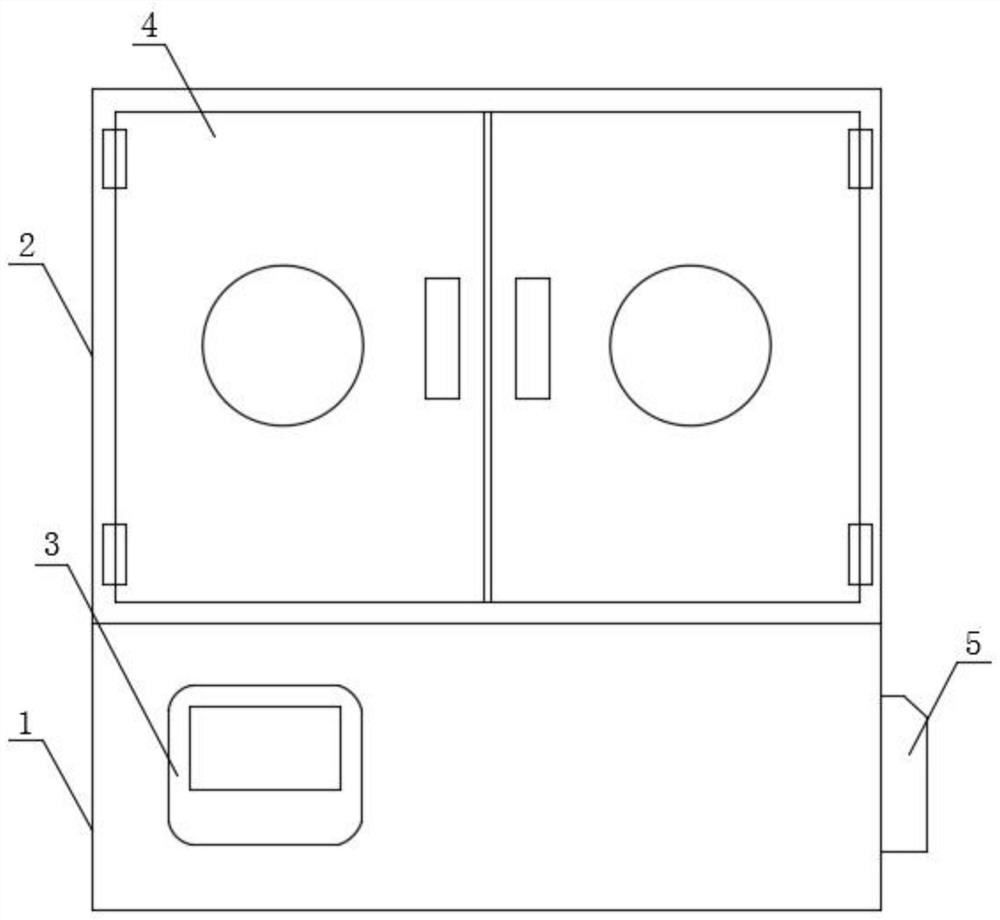
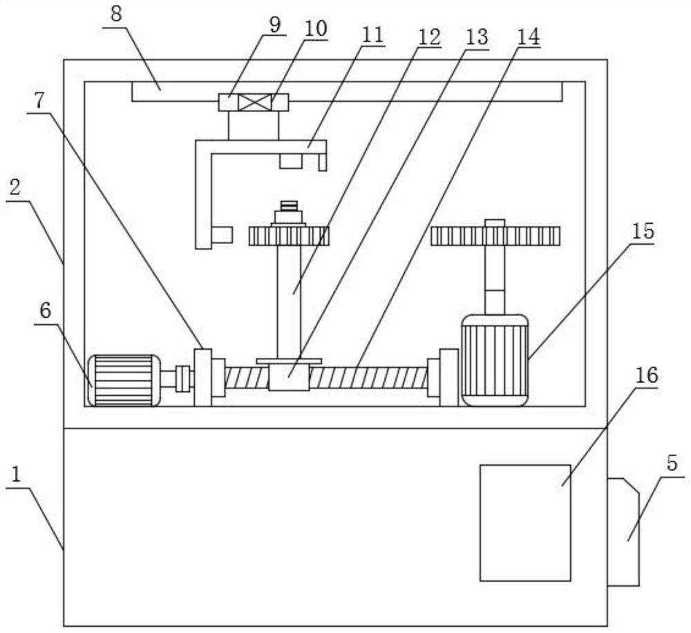
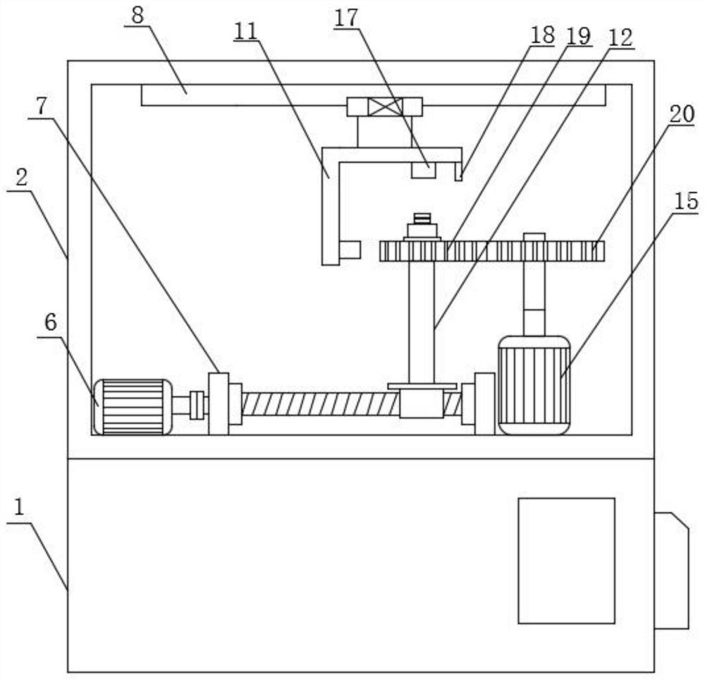
[0028] see figure 1 , image 3 , Figure 4 and Figure 5 , the present invention provides a technical solution: an overhaul system for gear flaw detection, comprising a base 1, a chassis 2 and a flaw detector, the chassis 2 is fixedly installed on the upper end of the base 1, and one side of the outer wall of the base 1 is fixedly installed There is a PLC controller 5, a box door is hinged on one side of the outer wall of the chassis 2, a No. 1 motor 6 and a bearing seat 7 are fixedly installed on one side of the inner bottom end of the chassis 2, and the bearing seat 7 is provided with two groups, two groups. A threaded rod 14 is rotatably installed between the bearing seats 7, a threaded sliding seat 13 is threadedly mounted on the external thread of the threaded rod 14, and a support rod 12 is fixedly installed on the upper end of the threaded sliding seat 13 through a holding plate. 12. The gear to be tested 19 is rotatably installed on the outside of the upper end, the...

Embodiment 2

[0039] see Figure 2-5 , the present invention provides a technical solution: an overhaul system for gear flaw detection, comprising a base 1, a chassis 2 and a flaw detector, the chassis 2 is fixedly installed on the upper end of the base 1, and one side of the outer wall of the base 1 is fixedly installed There is a PLC controller 5, a box door is hinged on one side of the outer wall of the chassis 2, a No. 1 motor 6 and a bearing seat 7 are fixedly installed on one side of the inner bottom end of the chassis 2, and the bearing seat 7 is provided with two groups, two groups. A threaded rod 14 is rotatably installed between the bearing seats 7, a threaded sliding seat 13 is threadedly mounted on the external thread of the threaded rod 14, and a support rod 12 is fixedly installed on the upper end of the threaded sliding seat 13 through a holding plate. 12. The gear to be tested 19 is rotatably installed on the outside of the upper end, the second motor 15 is fixedly installed...


PUM


Abstract

The invention discloses an overhaul system for gear flaw detection, comprising a base, a chassis and a flaw detector. The chassis is fixedly installed on the upper end of the base, and a PLC controller is fixedly installed on one side of the outer wall of the base. A box door is installed on the side hinge, a No. 1 motor and a bearing seat are fixedly installed on one side of the inner bottom end of the box, and there are two sets of bearing seats, a threaded rod is rotatably installed between the bearing seats, and the external thread of the threaded rod is A threaded sliding seat is installed, and a support rod is fixedly installed on the upper end of the threaded sliding seat through a holding plate; the drive gear installed in the present invention can not only perform static non-destructive flaw detection operation on the gear, but also timely discover the structural hidden danger in the production and processing of the gear, It can also perform structural flaw detection on gears under dynamic operation, which helps to grasp the force and deformation of the gear structure under operating conditions, and effectively improves the detection effect.

Description

technical field [0001] The invention relates to the technical field of gear flaw detection and detection, in particular to an overhaul system for gear flaw detection and detection. Background technique [0002] A gear is a mechanical element that continuously meshes with gears on the rim to transmit motion and power. The application of gears in transmission appeared very early. At the end of the 19th century, the principle of the gear cutting method and the special machine tools and tools that used this principle to cut teeth appeared one after another. With the development of production, the stability of gear operation has been paid attention to, and gears have a role in the power transmission of current various mechanical equipment. It has extremely extensive and irreplaceable functions. Therefore, the stability and structural strength of the gear structure are of great significance to the operation of mechanical equipment, especially in all large torque transmissions. Th...

Claims


Application Information

Patent Timeline
Patent Type & Authority Patents(China)
IPC IPC(8): G01N29/04G01N29/22G01N29/26G01N27/82
CPCG01N29/04G01N29/22G01N27/82G01N29/26G01N2291/0289G01N2291/2696
Inventor 夏曲夏冰心张长友唐崇邦
Owner BEIJING MAGNETIC FLUX EQUIP MFG
Learn More