
MBR sewage processing facility and method

A technology of sewage treatment equipment and sewage treatment methods, applied in biological water/sewage treatment, water/sludge/sewage treatment, special treatment targets, etc., can solve the problems of single purification effect, long cleaning cycle, difficult operation, etc. The effect of improving the purification effect and shortening the purification cycle

Active Publication Date: 2019-11-29
沈阳天净环保科技有限公司
View PDF3 Cites 0 Cited by
  • Summary
  • Abstract
  • Description
  • Claims
  • Application Information

AI Technical Summary

Problems solved by technology

[0004] 1. The working mode of sewage treatment is single, the scene adaptability is too poor, and the types of sewage that can be treated are too few, the purification effect is single, and often only one purification effect can be obtained for treated water, which is difficult to meet various needs;
[0005] 2. The sewage treatment efficiency is low, the sewage treatment cycle is long, and the practicability is poor;
[0006] 3. The cost of sewage treatment is high, the capital investment is huge, and it is difficult to promote it on a large scale;
[0007] 4. The MBR membrane cleaning process is cumbersome, difficult to operate, and the cleaning cycle is long, which wastes a lot of manpower and material resources, resulting in high MBR membrane cleaning costs;
[0008] 5. The MBR membrane is not cleaned cleanly, and in the cleaning project, accidents that cannot be used again due to the damage of the MBR membrane occur from time to time;
[0009] 6. The cost of sewage purification treatment is high, and it is difficult to promote and implement, etc.

Method used


Image

  • MBR sewage processing facility and method
  • MBR sewage processing facility and method
  • MBR sewage processing facility and method

Examples


Embodiment Construction

[0066] The present invention will be described in further detail below through specific embodiments and in conjunction with the accompanying drawings. It should be noted that, in the case of no conflict, the embodiments in the present application and the features in the embodiments can be combined with each other. In addition, the examples are illustrative, and are only for explaining the present invention, and should not be construed as limiting the present invention.

[0067] Structural analysis of the present invention:

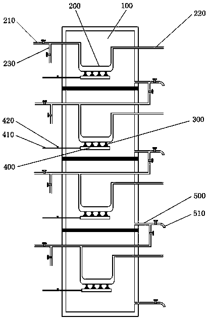
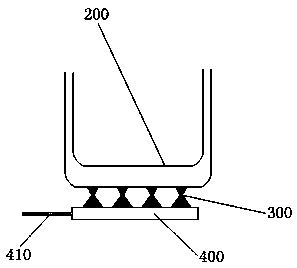
[0068] In one aspect, the present invention discloses a MBR sewage treatment equipment. According to an embodiment of the present invention, the equipment is provided with a purification tank, such as figure 1 and figure 2 As shown, the accommodating chamber of the purification tank separates multiple purification chambers (100), and the purification chambers (100) are all equipped with U-shaped MBR membrane tubes (200), sewage pipes (300), and sewage c...


PUM


Abstract

The invention discloses an MBR sewage processing facility and method. The MBR sewage processing facility is provided with a purification tank. The storage cavity of the purification tank is divided into a plurality of purification chambers. Each chamber is provided with a U shape MBR membrane pipe, a dirt pipe, a dirt collection pipe, and a recovering pipe. The diameter of the bent section of theU shape MBR membrane pipe is greater than the diameters of other sections. A water inlet pipe is connected to a clean water pipe. Two ends of the dirt pipe are connected to the bent section of the U shape MBR membrane pipe and the dirt collection pipe. From one end to the other end, the diameter of the dirt pipe gradually narrows down at first and then gradually becomes bigger. The dirt collectionpipe is connected to a cleaning suction pipe. The cleaning suction pipe is connected to a dirt suction pump. The diameter of the cleaning suction pipe is smaller than the diameter of the dirt collection pipe. The recovering pipe is connected to the water inlet pipe of the U shape MBR membrane pipe and is also connected to a graded water pipe. The kinds of MBR of U shape MBR membrane pipes arranged between purification chambers can be identical or different. The facility can work under three purification work modes, can meet various requirements, and has a wide application range.

Description

technical field [0001] The invention relates to the technical field of environmental protection, in particular to an MBR sewage treatment equipment and an MBR sewage treatment method. Background technique [0002] In the field of sewage treatment technology, MBR membrane (Membrane Bio-Reactor, membrane bioreactor) is a new water treatment technology that combines activated sludge method and membrane separation technology. There are many types of MBR membranes, which are classified according to the separation mechanism and are divided into reaction membranes, ion exchange membranes, permeable membranes, etc.; according to the properties of the membranes, they are divided into natural membranes (biological membranes) and synthetic membranes (organic membranes and inorganic membranes); According to the structural type of the membrane, it is divided into flat type, tubular type, spiral type and hollow fiber type. Among the many MBR membranes, the solid-liquid separation membran...

Claims


Application Information

Patent Timeline
Patent Type & Authority Applications(China)
IPC IPC(8): C02F3/12
CPCC02F3/1268C02F2303/14Y02W10/10
Inventor 张爱萍林海军王立庆
Owner 沈阳天净环保科技有限公司
Learn More