
Rotary mechanical vacuum flask and material preparation method thereof

A technology of rotating machinery and vacuum bottles, which is applied in the field of vacuum bottles, can solve the problems of uncontrollable liquid output, easy residues, and production and preparation of parts that are difficult to prevent ultraviolet rays and pressure-resistant materials, and achieve reasonable structural design, feasible production methods, and low residues. low rate effect

Pending Publication Date: 2019-11-29
ZHEJIANG Z&Z IND CO LTD
View PDF1 Cites 3 Cited by
  • Summary
  • Abstract
  • Description
  • Claims
  • Application Information

AI Technical Summary

Problems solved by technology

[0003] In order to overcome the above-mentioned shortcomings, the purpose of the present invention is to provide a rotary mechanical vacuum bottle and its material preparation method in the field, so that it can solve the problem that existing similar products are prone to residue when used, and the liquid output cannot be controlled (rotary quantitative), It is difficult to use anti-ultraviolet and pressure-resistant materials to produce technical problems in the preparation of components

Method used


Image

  • Rotary mechanical vacuum flask and material preparation method thereof
  • Rotary mechanical vacuum flask and material preparation method thereof
  • Rotary mechanical vacuum flask and material preparation method thereof

Examples


Embodiment 1

[0031] Embodiment 1: It includes the following preparation steps: 1), powder treatment: pour 5 parts of reinforced powder into a mixer equipped with a high-pressure sprayer by weight, and spray 0.2 parts by weight of the powder while stirring the powder. Silane coupling agent KH550, the pressure of the high-pressure sprayer is 0.5MPa, the stirring temperature is 60°C, and the stirring time is 35min; 2), extrusion granulation: 80 parts of modified polyethylene, 5 parts of graphene, 5 parts by weight 1 part of toughening agent, 2 parts of compatibilizer, 0.2 part of antioxidant, 0.2 part of antistatic agent, 0.5 part of lubricant are stirred evenly and enter the extruder barrel from the main feeding port of the twin-screw extruder, and the step 1) The processed reinforced powder enters the extruder barrel from the side feeding port of the twin-screw extruder and is mixed and extruded. The temperature in the extruder barrel is 180°C and the screw speed is 800r / min. After cooling ...

Embodiment 2

[0032] Embodiment 2: It includes the following preparation steps: 1), powder treatment: pour 50 parts of reinforced powder into a mixer equipped with a high-pressure sprayer by weight, and spray 0.1 part of powder while stirring the powder Silane coupling agent KH560, the pressure of the high-pressure sprayer is 0.6MPa, the stirring temperature is 80°C, and the stirring time is 25min; 2), extrusion granulation: 85 parts of modified polyethylene, 8 parts of graphene, 10 parts by weight 1 part of toughening agent, 8 parts of compatibilizer, 0.4 part of antioxidant, 0.5 part of antistatic agent, and 2 parts of lubricant are stirred evenly and enter the extruder barrel from the main feeding port of the twin-screw extruder, and the step 1) The processed reinforced powder enters the extruder barrel from the side feeding port of the twin-screw extruder and is mixed and extruded. The temperature in the extruder barrel is 230°C and the screw speed is 200r / min. After cooling in the cool...

Embodiment 3

[0033] Embodiment 3: It includes the following preparation steps: 1), powder treatment: pour 15 parts of reinforced powder into a mixer equipped with a high-pressure sprayer by weight, and spray 0.2 parts by weight of the powder while stirring the powder Silane coupling agent KH550, the pressure of the high-pressure sprayer is 0.8MPa, the stirring temperature is 65°C, and the stirring time is 32min; 2), extrusion granulation: 90 parts of modified polyethylene, 10 parts of graphene, 6 parts by weight 1 part of toughening agent, 4 parts of compatibilizer, 0.25 part of antioxidant, 0.25 part of antistatic agent, and 0.8 part of lubricant are stirred evenly and enter the extruder barrel from the main feeding port of the twin-screw extruder, and the step 1) The processed reinforced powder enters the extruder barrel from the side feeding port of the twin-screw extruder and is mixed and extruded. The temperature in the extruder barrel is 200°C and the screw speed is 600r / min. After c...


PUM

PropertyMeasurementUnit
particle size (mesh)aaaaaaaaaa

Abstract

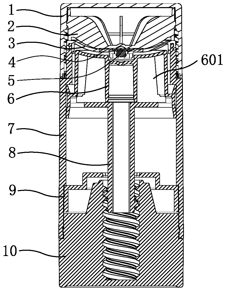
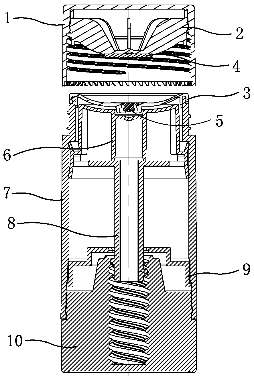
The invention relates to a rotary mechanical vacuum flask and a material preparation method thereof. Aiming at the technical problem that residual is easily generated when existing like products are used, the liquid discharge amount cannot be controlled, and parts are difficult to produce and prepare through adopting an ultraviolet-proof pressure-resistant material, the rotary mechanical vacuum flask is designed. The rotary mechanical vacuum flask is characterized in that a bottom cover is arranged at the bottom of an outer flask of the vacuum flask, an inner plug is arranged in the outer flask at the bottom cover end, and a press cover for sealing, buckling and fixing is arranged at an inner flask opening of the outer flask. The main points are that a screw hole is formed in the center ofthe bottom cover in the outer flask, and the bottom cover is fixed to the bottom of the outer flask to rotate; a threaded rib at one end of a screw rod is connected with the screw hole of the bottomcover through a through hole in the center of the inner plug, a channel hole is formed in a center shaft of the screw rod, and the other end of the screw rod abuts against the bottom of a piston in the outer flask; and a plug is fixed to a center hole of the press cover in a buckled mode, the outer diameter of the inner plug abuts against the inner wall of the outer flask, a liquid outlet gap is formed between the press cover of an end opening of the outer flask and the plug, and the piston is driven to lift to move up by the screw rod until a step edge ring opening of the inner plug and a ring opening at the outer diameter of a step rib of the outer flask are limited in an abutting mode.

Description

technical field [0001] The invention relates to a vacuum bottle, which is a rotating mechanical vacuum bottle and a material preparation method thereof. Background technique [0002] The vacuum bottle refers to a container that can isolate the gas from the external temperature or the container that isolates the external bacteria. The vacuum bottle sold on the market is composed of a cylinder into an ellipsoid container and a piston placed at the bottom. Its working principle is to use the contraction force of the spring, and prevent air from entering the bottle to form a vacuum state, and use atmospheric pressure to push the piston at the bottom of the bottle forward. Existing vacuum bottles are used in daily chemical packaging and skin care products. The vacuum bottles on the market are basically pumped out, and a leak-proof pad is provided between the inner cover and the gland to prevent liquid leakage during normal carrying. The tablet plays a role of convenience and saf...

Claims


Application Information

Patent Timeline
Patent Type & Authority Applications(China)
IPC IPC(8): B65B41/04B65D1/06B65D39/00B65D47/06B65D83/00C08L23/26C08L51/00C08L23/08C08K3/34C08K7/20C08K7/12C08K3/04
CPCB65D1/06B65B41/04B65D39/00B65D47/06B65D83/0011C08L23/26C08L51/06C08L23/0815C08L23/0869C08L23/0853C08K3/34C08K7/20C08K7/12C08K3/042
Inventor 黄建艺
Owner ZHEJIANG Z&Z IND CO LTD
Learn More