Grinding machine with positioning device for preventing sweeps from splashing

A technology of positioning device and grinding machine, which is applied in the direction of grinding machine, grinding bed, grinding/polishing safety device, etc., can solve the problems of adjusting the protection range of the protective cover, complicated structure and difficult operation, etc.

Inactive Publication Date: 2019-11-29
HEFEI E CHON METAL PLATE TECH CO LTD
View PDF14 Cites 3 Cited by
  • Summary
  • Abstract
  • Description
  • Claims
  • Application Information

AI Technical Summary

Problems solved by technology

Most CNC grinding machines use high-speed rotating grinding wheels for grinding, and a few use other abrasive tools such as oil stones, abrasive belts, and free abrasives for processing. During the processing, people need to be close to the grinding wheel to control the grinding degree of the workpiece. When the grinding wheel grinds the workpiece, the splashed workpiece chips will splash around, which obviously poses a safety hazard. In addition, the internal structure of the traditional CNC grinding machine is complicated and the operation is not easy. Sand dust and metal shavings can hurt the eyes of the workers. If the workers inhale this dust in a large amount, it will be harmful to the body. Although there is a protective cover in the prior art to cover the grinding wheel, the protective range of the protective cover cannot be based on the metal plate. The actual size is adjusted, resulting in the splashing of waste chips, so we provide a grinding machine with a positioning device to prevent the splashing of waste chips to solve the problems raised in the above-mentioned background technology

Method used


Image

  • Grinding machine with positioning device for preventing sweeps from splashing
  • Grinding machine with positioning device for preventing sweeps from splashing
  • Grinding machine with positioning device for preventing sweeps from splashing

Examples


Embodiment Construction

[0022] The following will clearly and completely describe the technical solutions in the embodiments of the present invention with reference to the accompanying drawings in the embodiments of the present invention. Obviously, the described embodiments are only some, not all, embodiments of the present invention. Based on the embodiments of the present invention, all other embodiments obtained by persons of ordinary skill in the art without making creative efforts belong to the protection scope of the present invention.

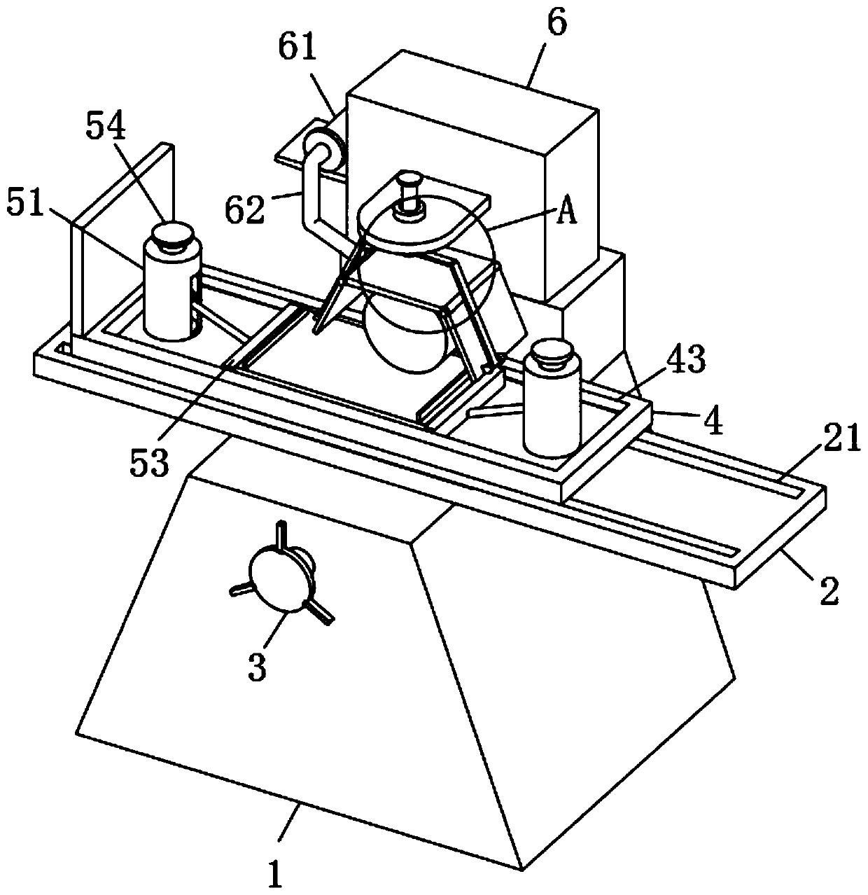
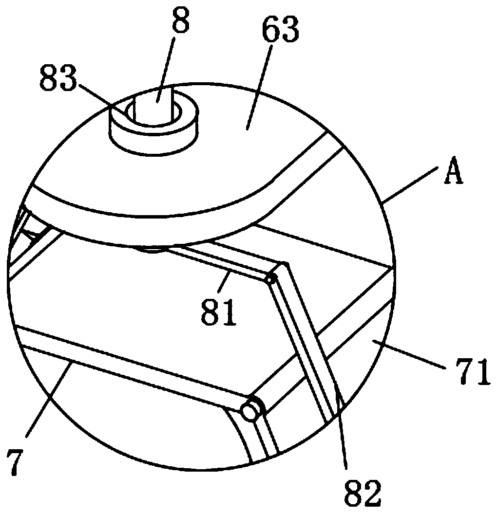
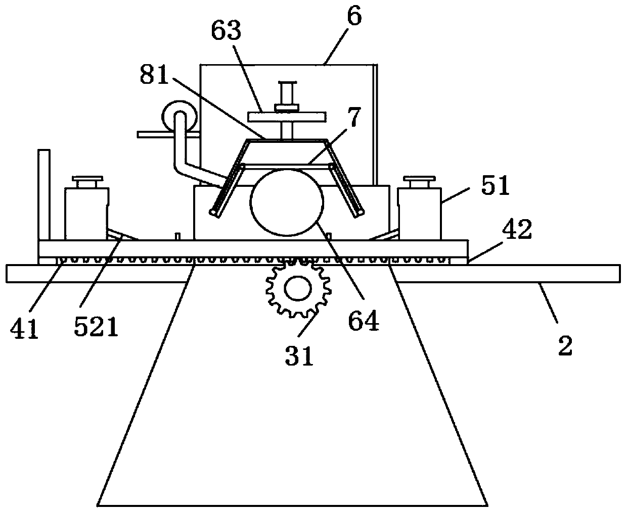
[0023] see Figure 1-4 , the present invention provides a technical solution: a grinding machine with a positioning device to prevent waste from splashing, including a base 1, a bed 6, a carriage 4 and a protective cover 7, and the upper surface of the base 1 is welded with a support plate 2 , the carriage 4 is movably arranged on the upper surface of the support plate 2, and a rotating rod is inserted into one side of the base 1 for rotation, and one end of t...


PUM


Abstract

The invention discloses a grinding machine with a positioning device for preventing sweeps from splashing. The grinding tool comprises a base, a machine bed, a sliding frame and a protection cover. Asupporting plate is welded to the upper surface of the base, and the sliding frame is movably arranged on the upper surface of the supporting plate. A rotary rod is rotationally inserted into one side of the base, and a gear is welded to one end of the rotary rod. A first lead screw is pushed, so that the first lead screw extrudes a movable ring downwards, a guide rod is stressed and pushes a push plate to slide at this moment, and finally the end of a workpiece is clamped. One end of a spring is connected with the upper surface of the movable ring, the height of the movable ring in a limiting frame can be adjusted conveniently, and finally the position of the push plate on the surface of the sliding frame is controlled. By changing the position of a first connecting rod, so that one endof a second connecting rod drives the included angle between the one end of a protection plate and the protection cover to change, and therefore the surfaces of workpieces with different lengths are covered, and the situation of sweep splashing is avoided.

Description

technical field [0001] The invention relates to the technical field of grinding machines, in particular to a grinding machine with a positioning device for preventing waste chips from splashing. Background technique [0002] With the rapid development of the industrial level, people are processing workpieces more and more finely. The traditional grinding machine is a machine tool that uses abrasive tools to grind the surface of the workpiece. Most CNC grinding machines use high-speed rotating grinding wheels for grinding, and a few use other abrasive tools such as oil stones, abrasive belts, and free abrasives for processing. During the processing, people need to be close to the grinding wheel to control the grinding degree of the workpiece. When the grinding wheel grinds the workpiece, the splashed workpiece chips will splash around, which obviously poses a safety hazard. In addition, the internal structure of the traditional CNC grinding machine is complicated and the oper...

Claims


Application Information

Patent Timeline
IPC IPC(8): B24B27/00B24B55/04B24B55/00B24B41/06B24B41/02
CPCB24B27/00B24B27/0092B24B41/02B24B41/06B24B55/00B24B55/04
Inventor 陆飞飞
Owner HEFEI E CHON METAL PLATE TECH CO LTD
Why Eureka
Try Eureka