
An Automatic Deburring Mechanism for Machining Gearbox Shell

A technology of deburring mechanism and gearbox, which is applied to machine tools, metal processing equipment, manufacturing tools and other directions suitable for grinding workpiece edges, can solve problems such as damage, low adaptability, pollution, etc., and achieve smooth adjustment and movement. Precise location, precision and high quality results

Active Publication Date: 2021-03-16
LIUAN LONGXING AUTO PARTS
View PDF7 Cites 0 Cited by
  • Summary
  • Abstract
  • Description
  • Claims
  • Application Information

AI Technical Summary

Problems solved by technology

[0004] The purpose of the present invention is to solve the problem that the existing automatic deburring mechanism for gearbox casing processing is slow in removing burrs from the bottom, side and upper end faces of the gearbox casing, and the removal is not comprehensive enough; and the existing deburring mechanism works The degree of automation is low, and it is time-consuming and laborious to use; the deburring mechanism can only deburr the gearbox casing with the same width and height, and the work adaptability is low; the smoothness of the various components on the deburring mechanism is poor when adjusting. Not only is the position of the deburring work on the gearbox casing inaccurate and suitable, but it also leads to violent collisions between various components and the gearbox casing, resulting in damage; when the deburring mechanism deburrs the gearbox casing, the removed burrs It is easy to fly into the air and cause environmental pollution, and the deburring mechanism cannot recycle the removed burrs, so an automatic deburring mechanism for gearbox shell processing is proposed

Method used


Image

  • An Automatic Deburring Mechanism for Machining Gearbox Shell
  • An Automatic Deburring Mechanism for Machining Gearbox Shell
  • An Automatic Deburring Mechanism for Machining Gearbox Shell

Examples


Embodiment Construction

[0046] The technical solutions of the present invention will be clearly and completely described below in conjunction with the embodiments. Apparently, the described embodiments are only some of the embodiments of the present invention, not all of them. Based on the embodiments of the present invention, all other embodiments obtained by persons of ordinary skill in the art without creative efforts fall within the protection scope of the present invention.

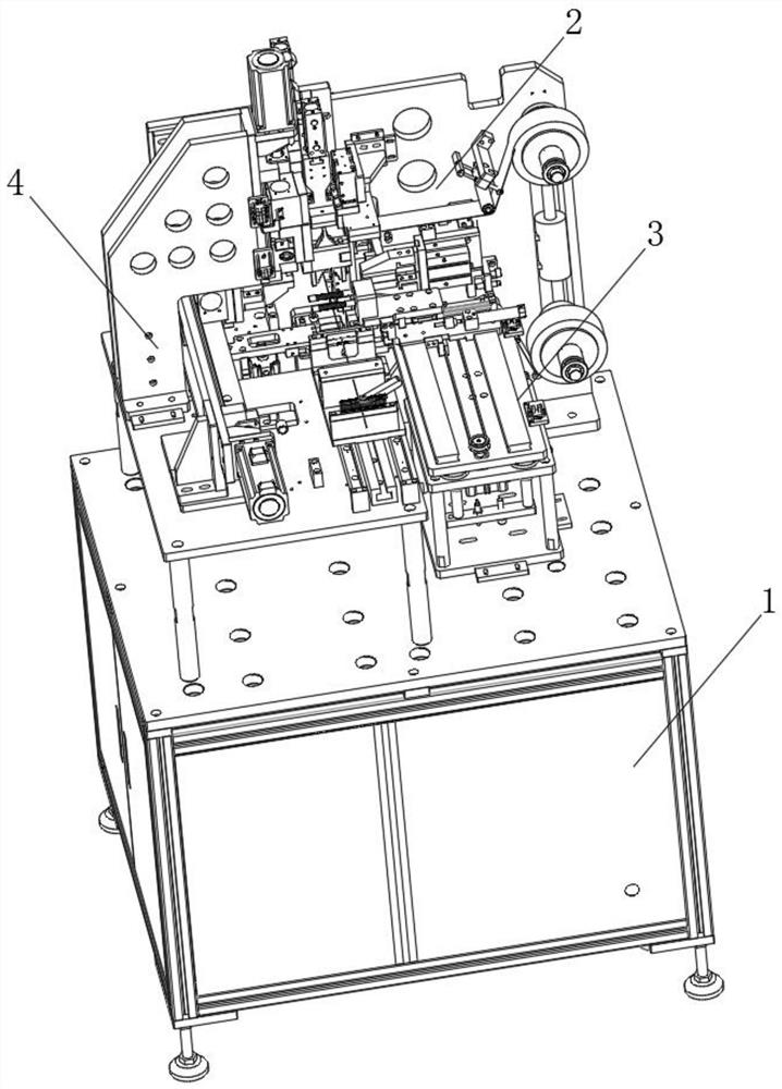
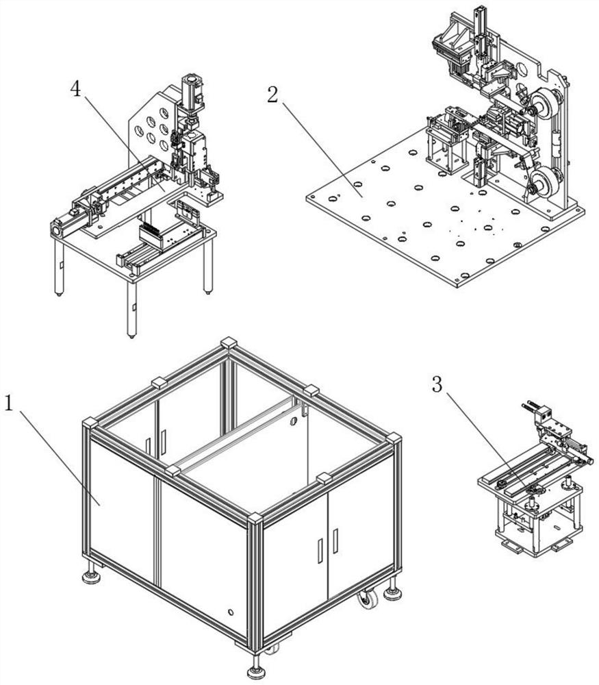
[0047] see Figure 1-12 As shown, an automatic deburring mechanism for gearbox casing processing, including a supporting box 1, a supporting platform 2, a loading platform 3 and a side repair seat 4, the supporting platform 2 is arranged above the supporting box 1, and the supporting box One end of the inner side of the table 2 is provided with a loading table 3, and the other end of the inner side of the supporting table 2 is provided with a side repair seat 4;

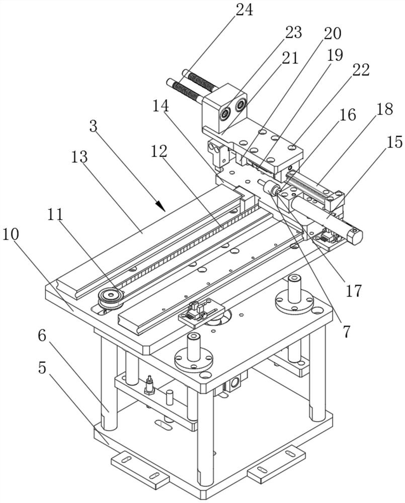
[0048] The bottom of the loading table 3 is horizontally pr...


PUM


Abstract

The invention discloses an automatic deburring mechanism applied to machining of a gearbox housing. The automatic deburring mechanism comprises a bracing box, a support platform, a carrying platform and a side repairing seat; the support platform is arranged above the bracing box; the carrying platform is arranged at one end of the inner side of the support platform; the side repair seat is arranged at the other end of the inner side of the support platform; the bottom of the carrying platform is horizontally provided with a rectangular base plate; the corners of the upper end faces of the base plate are each vertically provided with a strut; a supporting plate I is vertically arranged at the tops of the struts; a hydraulic pump I is used for driving a scraping and grinding cylinder I to stretch in the front-rear direction to regulate the position by virtue of a hydraulic column I and cooperates with a motor V to drive a gearbox housing to be rotationally regulated by virtue of a gearI; a motor IV is arranged at a sliding rail II in a sleeving manner in order to drive the gearbox housing to be movably regulated in position; at one hand, the automatic deburring mechanism can guarantee more precise working positions for polishing and deburring at the lower portions of the gearbox housings which are different in width and size; and on the other hand, the work efficiency of deburring and the comprehensiveness of deburring, at the lower portion of each gearbox housing, of the mechanism are greatly improved.

Description

technical field [0001] The invention relates to a deburring mechanism, in particular to an automatic deburring mechanism used for processing a gearbox casing, and belongs to the technical field of deburring mechanism applications. Background technique [0002] The gearbox casing can protect the gearbox very well, greatly improving the durability of the gearbox. The deburring mechanism is indispensable in the processing of the gearbox casing. The deburring mechanism can remove the burr from the gearbox casing. It not only improves the comfort of the gearbox shell during use, but also improves the fit with the gearbox during assembly. [0003] The existing automatic deburring mechanism for gearbox casing processing is slow in removing burrs from the bottom, side, and upper surfaces of the gearbox casing, and the removal is not comprehensive enough, and the existing deburring mechanism has a low degree of automation, and it is time-consuming and laborious to use , the deburrin...

Claims


Application Information

Patent Timeline
Patent Type & Authority Patents(China)
IPC IPC(8): B24B9/00B24B27/00B24B47/22B24B41/06B24B41/02B24B47/04B24B21/00B24B21/20B24B55/06B24B55/12
CPCB24B9/00B24B21/00B24B21/20B24B27/0076B24B41/02B24B41/06B24B47/04B24B47/22B24B55/06B24B55/12
Inventor 张传如
Owner LIUAN LONGXING AUTO PARTS
Learn More