
Flat plate folding and unfolding unit and flat plate folding and unfolding antenna mechanism

A folding mechanism and flat panel technology, which is applied in the field of aerospace vehicles, can solve the problems of not many flat panels for deployable mechanism units, and achieve the effects of rich design types, simple and reasonable structure, and improved support rigidity

Active Publication Date: 2019-11-26
YANSHAN UNIV
View PDF7 Cites 7 Cited by
  • Summary
  • Abstract
  • Description
  • Claims
  • Application Information

AI Technical Summary

Problems solved by technology

[0004] It can be seen from the above that the current research on the expandable mechanism mainly focuses on the kinematics and dynamics of the mechanism, but there are not many designs on the design of the expandable mechanism itself, especially the unit design of the flat-plate folding mechanism.

Method used


Image

  • Flat plate folding and unfolding unit and flat plate folding and unfolding antenna mechanism
  • Flat plate folding and unfolding unit and flat plate folding and unfolding antenna mechanism
  • Flat plate folding and unfolding unit and flat plate folding and unfolding antenna mechanism

Examples


Embodiment 1

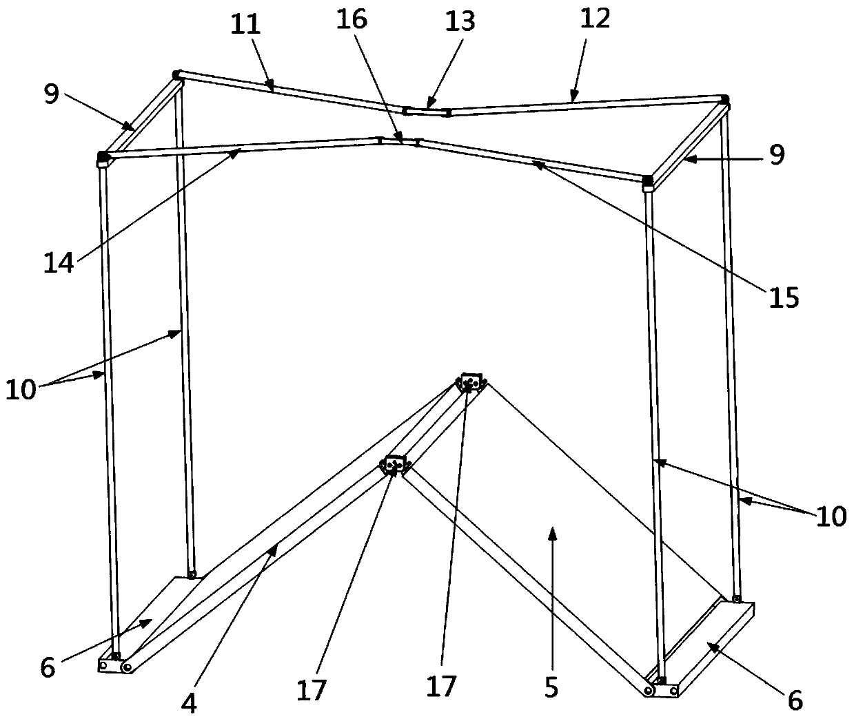
[0045] Such as Figure 1-11 As shown, the present embodiment provides a flat panel folding unit 1, including a folding mechanism 2 and a supporting mechanism side 3, the folding mechanism 2 includes a first antenna panel 4 and a second antenna panel 5, the first antenna panel 4 and the second antenna panel 5 Two antenna panels 5 are hinged to form the first rotary pair, the free side of the first antenna panel 4 and the free side of the second antenna panel 5 are respectively hinged with the lower connecting plate 6 to form the second rotary pair, and the axis of the second rotary pair is parallel to The axis of the first rotating pair, and the axes of these two rotating pairs are parallel to the sidelines of the above two antenna plates; if figure 1 As shown, the support mechanism side 3 includes a first folding assembly 7, a second folding assembly 8 and an upper connecting plate 9, and the two ends of the first folding assembly 7 pass through an upper connecting plate 9 and...

Embodiment 2

[0056] Such as Figure 12 and 13 As shown, this embodiment discloses a flat-panel folding antenna mechanism 23, which includes a plurality of flat-panel folding units 1 with a quadrangular prism structure when unfolded as described in Embodiment 1, the specific structural composition and working principle of the flat-panel folding unit 1 Embodiment 1 has already been disclosed and will not be repeated here.

[0057] Such as Figure 12 As shown, a plurality of flat-panel folding units 1 are connected in sequence, and every two adjacent flat-panel folding units 1 share two vertical support rods 10 and two vertical support rods between the two flat-panel folding units 1 10 the upper connecting plate 9 and the lower connecting plate 6 connected at both ends; The axes of the expansion components 7 are collinear, and the axes of the second expansion components 8 between the flat panel folding units 1 are collinear. Such as Figure 13It is shown that the flat panel folding anten...


PUM


Abstract

The invention discloses a flat plate folding and unfolding unit. The flat plate folding and unfolding unit comprises a folding and unfolding mechanism and a support mechanism side, wherein the supportmechanism side is above the folding and unfolding mechanism; the support mechanism side is connected with the folding and unfolding mechanism through a vertical support rod; components of the flat plate folding and unfolding unit are connected directly through revolute pairs, so that the structure is simple and reasonable; a folding and unfolding direction of the support mechanism side is fully vertical to the folding and unfolding direction of an antenna flat plate, so that the support rigidity is improved, and the unit unfolding structure is more stable. The invention further discloses a flat plate folding and unfolding antenna mechanism. The mechanism is formed by connecting the plurality of flat plate folding and unfolding units; the flat plate folding and unfolding units are totallyidentical and are symmetrical in structure; and the flat plate folding and unfolding units are directly connected without auxiliary pieces, thereby being convenient to manufacture and assemble, expanding strongly, being capable of making up large flat plate folding and unfolding antenna mechanisms in any length contracting highly according to needs, and being highly practical.

Description

technical field [0001] The invention belongs to the technical field of aerospace vehicles, and in particular relates to a flat-panel folding unit and a flat-panel folding antenna mechanism. Background technique [0002] With the in-depth exploration of the mysteries of the universe, aerospace technologies such as super-large and high-precision satellites and space stations occupy an important position in various fields. The space unfolding structure is generally in the folded state on the ground and during the launch process. When the spacecraft is positioned on the working orbit and is ready, the driving device will make it unfold into the preset working state. At present, various spacecrafts have widely used this folding structure. However, due to the limited storage capacity of ground-based space launchers, aerospace engineering is more and more urgent for the further development of various space foldable structures. [0003] The research on plane folding mechanism has ...

Claims


Application Information

Patent Timeline
IPC IPC(8): H01Q1/12H01Q1/08
CPCH01Q1/08H01Q1/1235
Inventor 许允斗郭路瑶李明韩博路斯成崔琦峰姚建涛赵永生
Owner YANSHAN UNIV
Learn More