Anti-corrosion fluid conveying machine for chemical production

A technology of fluid conveying and chemical production, applied in the field of anti-corrosion fluid conveying machinery, can solve the problems of reduced practicability, easy to corrode impeller, equipment damage, etc., to achieve the effect of improving practicability, avoiding contact corrosion, and ensuring air circulation

Inactive Publication Date: 2019-11-26
特尼格日
View PDF7 Cites 1 Cited by
  • Summary
  • Abstract
  • Description
  • Claims
  • Application Information

AI Technical Summary

Problems solved by technology

[0003] Traditional liquid conveying machinery, that is, during the operation of the pump, most of them rely on the rotation of the impeller to generate negative pressure. The liquid is sucked into the pump casing and then discharged from the discharge pipe. The impeller is in contact with the liquid. The remaining part transports the liquid, and these liquids are in contact with the impeller, which is easy to corrode the impeller and reduce the transport efficiency of the liquid transport machinery. After long-term use, it will also cause equipment damage, which in turn will reduce the practicability of the existing chemical production fluid transport machinery

Method used


Image

  • Anti-corrosion fluid conveying machine for chemical production
  • Anti-corrosion fluid conveying machine for chemical production
  • Anti-corrosion fluid conveying machine for chemical production

Examples


Embodiment Construction

[0024] The present invention is described in further detail now in conjunction with accompanying drawing. These drawings are all simplified schematic diagrams, which only illustrate the basic structure of the present invention in a schematic manner, so they only show the configurations related to the present invention.

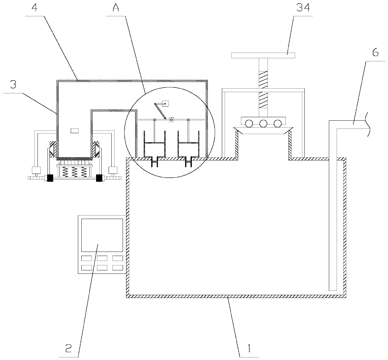
[0025] Such as figure 1 As shown, a kind of anti-corrosion fluid conveying machinery used in chemical production includes a material box 1, a controller 2, an air inlet pipe 3, a horizontal pipe 4, a vertical pipe 5, a liquid outlet pipe 6 and a liquid injection mechanism. The liquid mechanism is arranged above the material box 1, the bottom end of the vertical pipe 5 is fixed above the material box 1, one end of the horizontal pipe 4 communicates with the top of the vertical pipe 5, and the top of the air inlet pipe 3 is connected to the horizontal pipe 5. The other end of the pipe 4 is connected, the vertical pipe 5 is provided with a compression mechanism,...


PUM


Abstract

The invention relates to an anti-corrosion fluid conveying machine for chemical production. The machine comprises a material box, a controller, an air inlet pipe, a transverse pipe, a vertical pipe, aliquid outlet pipe and a liquid injection mechanism. A compression mechanism comprises a swing assembly, a swing rod and two compression assemblies, wherein the compression assembly comprises a compression pipe, an air injection pipe, a compression plate, a vertical rod and a lantern ring; and a purification mechanism comprises a filter screen, a rotating assembly, a cross rod, a circular ring, arotating rod and a plurality of springs. According to the anti-corrosion fluid conveying machine for chemical production, the compression plate continuously presses a solution in the material box into the liquid outlet pipe through taking air as a medium through the compression mechanism, so that the conveying function is realized, and the compression plate is prevented from being corroded due tothe contact with the solution; moreover, the air entering the vertical pipe is purified through a filtering mechanism, the rotating rod can be driven to rotate through the rotating assembly, the filter screen is cleaned and dredged, and it is ensured that the air circulation is smooth, so that the practicability of the equipment is further improved.

Description

technical field [0001] The invention relates to the field of chemical production equipment, in particular to an anti-corrosion fluid conveying machine for chemical production. Background technique [0002] In the chemical production process, fluid transportation is the most common and even indispensable unit operation. Fluid conveying machinery is a device that does work to the fluid to increase the mechanical energy of the fluid. Therefore, after the fluid conveying machinery is running, the fluid can obtain energy to overcome the loss of mechanical energy along the fluid conveying process, increase the potential energy and increase the liquid pressure (or decompression, etc. ). Generally, the machinery that transports liquid is called a pump; the machine that transports gas is called a fan, blower, compressor and vacuum pump according to the pressure it generates. [0003] Traditional liquid conveying machinery, that is, during the operation of the pump, most of them rel...

Claims


Application Information

Patent Timeline
Patent Type & Authority Applications(China)
IPC IPC(8): F04F1/00B01D46/10B01D46/00
CPCF04F1/00B01D46/10B01D46/681
Inventor 特尼格日
Owner 特尼格日
Why Eureka
Try Eureka