Detection device capable of automatically focusing and corresponding automatic focusing method

A detection device and automatic focusing technology, which is applied in the direction of measuring device, installation, and material analysis through optical means, can solve the problems of high cost, high hardware and software requirements, etc., to save manufacturing and use costs, and reduce the amount of communication data , The effect of accurately determining the focus position

Pending Publication Date: 2019-11-22
TARGETINGONE TECH (BEIJING) CORP +1
View PDF0 Cites 4 Cited by
  • Summary
  • Abstract
  • Description
  • Claims
  • Application Information

AI Technical Summary

Problems solved by technology

[0003] For the microfluidic chip, the micro-droplets are required to flow through the detection area in a line-by-line manner, so the width of the detection channel (21) is close to the diameter of the micro-droplets. For the early detection, the objective lens is required to emit the light source Focus the parallel light so that the focus is just on the horizontal plane of the chip channel. At this time, the detection signal sensitivity and signal strength are the best. This requires the objective lens to be able to control to achieve automatic focus. At present, in order to achieve automatic focus, it is mostly used at the position of the light source. Add an imaging device, take pictures of the chip channel in real time, then adjust the vertical position of the objective lens, and determine the focus position according to the clarity of the returned channel picture. This focusing method requires the installation of relatively expensive imaging equipment and relies on relatively high The transmission of big data also requires the computer to have a relatively complex image processing and analysis algorithm, that is, the current detection device or method has high requirements for the hardware and software of the equipment, resulting in a relatively high cost

Method used


Image

  • Detection device capable of automatically focusing and corresponding automatic focusing method
  • Detection device capable of automatically focusing and corresponding automatic focusing method

Examples


Embodiment Construction

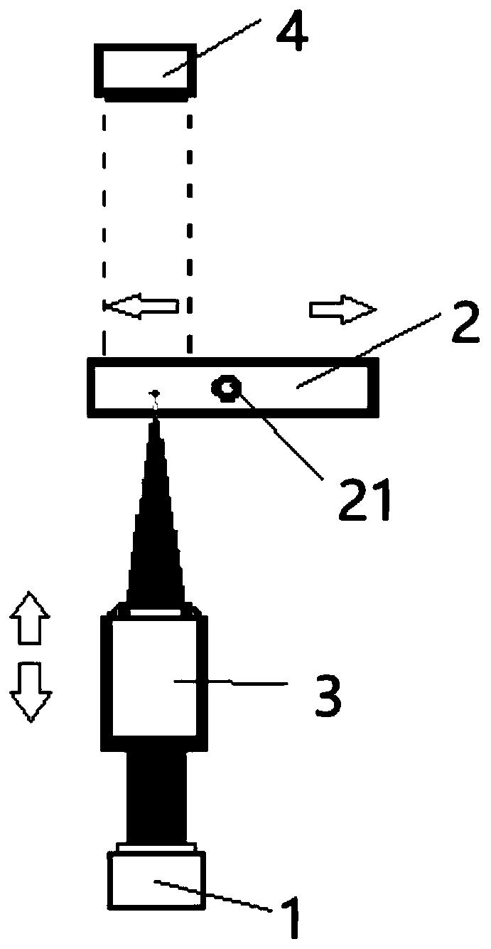
[0021] see in conjunction Figure 1 to Figure 2 As shown, according to an embodiment of the present invention, a detection device capable of autofocus is provided, including: a laser emission source 1 for generating parallel light beams; a detection chip 2 having a detection area plane on it, and a detection area plane A detection channel 21 is configured to carry micro-droplets to be detected, and the position of the detection chip 2 relative to the laser emission source 1 in the horizontal direction can be adjusted. It can be understood that the detection chip 2 is relatively Translational motion is generated in the laser emitting source 1, so that the laser light generated by the laser emitting source 1 can be irradiated on different areas of the detection chip 2, and can pass through the detection channel 21; the objective lens 3 is located in the Between the laser emitting source 1 and the detection chip 2, it is used to focus the parallel light beam; the light intensity ...


PUM


Abstract

The invention provides a detection device capable of automatically focusing and an automatic focusing method. The detection device comprises a laser emission source, a detection chip, an objective lens, a light intensity detection module, an operation control module and an objective lens height adjusting component, wherein the objective lens is positioned between the laser emission source and thedetection chip and used for focusing parallel beams; the light intensity detection module is arranged opposite to the objective lens so as to receive and detect the light intensity of the parallel light beams after passing through the objective lens and the detection chip; the operation control module is in communication connection with the light intensity detection module and used for receiving asignal detected by the light intensity detection module and performing operation to obtain the light intensity change range; and the objective lens height adjusting component is in control connectionwith the operation control module to obtain the light intensity change range and adjust the relative height between the objective lens and the detection chip according to the light intensity change range so as to enable the parallel light beams to be focused on the detection area plane. The detection device is relatively small in communication data volume, low in requirement on hardware and software of equipment and capable of saving the manufacturing and using cost.

Description

technical field [0001] The invention belongs to the technical field of micro-droplet chip detection, and in particular relates to a detection device capable of automatic focusing and a corresponding automatic focusing method. Background technique [0002] Micro-droplet microfluidics (droplet-based microfluidics) is a technology platform developed on microfluidic chips in recent years to manipulate small-volume liquids. Its principle is: combine two immiscible liquids, such as One of them is the oil phase, and the other is the water phase. After the oil phase and the water phase enter the microchannel at the same time, under the action of the microchannel, the water phase is formed in a small volume (10 -15 ~10 -9 L) The unit is distributed in the oil phase to form a series of discrete micro-droplets, and each droplet is used as a micro-reactor to complete a set of chemical or biological reactions. [0003] For the microfluidic chip, the micro-droplets are required to flow ...

Claims


Application Information

Patent Timeline
Patent Type & Authority Applications(China)
IPC IPC(8): G01N21/01G02B7/28
CPCG01N21/01G02B7/28
Inventor 苏世圣杜晓纯程昕刘晓彬白宇郭永
Owner TARGETINGONE TECH (BEIJING) CORP
Why Eureka
Try Eureka