
Combined gas-liquid separator structure

A gas-liquid separator and cylinder technology, which is applied in the field of air-conditioning components, can solve the problems that affect the smooth progress of debugging or maintenance, cannot add refrigerant or lubricating oil, and the liquid level is not easy to maintain uniformity, etc., so as to improve production or maintenance efficiency , Simple structure, reasonable design effect

Inactive Publication Date: 2019-11-19
NANJING TICA AIR CONDITIONING CO LTD
View PDF6 Cites 0 Cited by
  • Summary
  • Abstract
  • Description
  • Claims
  • Application Information

AI Technical Summary

Problems solved by technology

However, when two sub-gas-liquid separators are combined in parallel to form a larger gas-liquid separator, the liquid levels of the two sub-gas-liquid separators are not easy to maintain uniformity, which affects the use effect
Moreover, during on-site commissioning or after-sales maintenance operations, it is impossible to evenly add refrigerant or lubricating oil to the two sub-gas-liquid separators, or evenly discharge the refrigerant or lubricating oil in the two sub-gas-liquid separators, Affects the smooth progress of commissioning or maintenance, and urgently needs improvement

Method used


Image

  • Combined gas-liquid separator structure
  • Combined gas-liquid separator structure

Examples


Embodiment 1

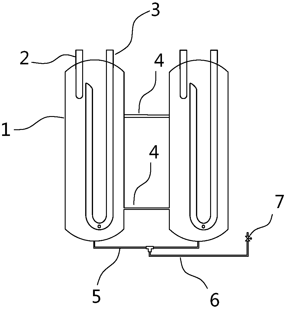
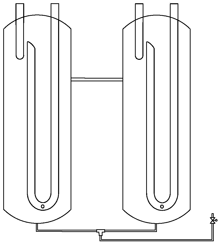
[0017] A combined gas-liquid separator structure includes two gas-liquid separators. The two gas-liquid separators have the same structure, including a cylinder body 1 , an inlet pipe 2 and an outlet pipe 3 . The inlet pipe 2 is a straight pipe extending from the top cover of the cylinder body 1 to the upper part of the cylinder body 1 from outside to inside. The outlet pipe 3 is a U-shaped pipe, its inlet end is located on the upper part of the cylinder body 1, and its outlet end protrudes from the top cover of the cylinder body 1, and is connected to the compressor. When the refrigerant containing gas and liquid enters the cylinder through the inlet pipe, it is stratified under the action of centrifugal force and gravity, and the liquid refrigerant sinks to the lower part of the gas-liquid separator, while the gas refrigerant is located The upper part of the cylinder flows out of the cylinder through the outlet pipe and returns to the compressor. The bottom of the outlet p...

Embodiment 2

[0021] This embodiment is basically the same as the first embodiment, the main difference is that there is one balance pipe in this embodiment, which is located at 1 / 2--5 / 6 of the height of the cylinder. At the same time, the diameter of the communication pipe in this embodiment is larger than that of the oil injection pipe, so that the communication pipe can allow the liquids in the two cylinders to communicate with each other, so that the liquid level between the cylinders is uniform, thus, a balance can be saved. tube, saves materials, simplifies the production process and reduces the cost.

[0022] The present invention maintains the liquid levels in a plurality of gas-liquid separators uniformly by arranging coil pipes, and fully satisfies the operation requirements of large-capacity units. At the same time, through the arrangement of the connecting pipe and the oil injection pipe, the refrigerant or lubricating oil can be added or discharged evenly during debugging or ma...


PUM


Abstract

The invention relates to a combined gas-liquid separator structure. The combined gas-liquid separator structure comprises two gas-liquid separators, wherein each gas-liquid separator comprises a barrel body, and inlet pipes and outlet pipes are arranged in the barrel bodies, balancing pipes communicates with the cylinder bodies are arranged between the side walls of all cylinder bodies; communicating pipes communicates with the cylinder bodies are arranged between the bottoms of all cylinder bodies, oil injection pipes are communicates with the communicating pipes so as to be used for emptyingor injecting liquid refrigerant or lubricating oil in the barrel bodies. The combined gas-liquid separator structure is reasonable in design, simple in structure and convenient to use, the liquid level in the multiple gas-liquid separators can be kept uniform, and the operation requirements of a large-capacity unit can be fully met. Meanwhile, the refrigerant or lubricating oil can be added or discharged uniformly during debugging or maintenance operation, so that the production or maintenance efficiency is improved.

Description

technical field [0001] The invention relates to an air-conditioning component, in particular to a gas-liquid separation device, in particular to a combined gas-liquid separator structure. Background technique [0002] As the capacity of the refrigeration system increases, the refrigerant required by the system also gradually increases, so a larger gas-liquid separator needs to be selected. At present, the methods for increasing the volume of the gas-liquid separator include increasing the volume of a single gas-liquid separator or adopting the form of parallel connection of multiple gas-liquid separators. However, when two sub-gas-liquid separators are combined in parallel to form a larger gas-liquid separator, the liquid levels of the two sub-gas-liquid separators are not easy to maintain uniformity, which affects the use effect. Moreover, during on-site commissioning or after-sales maintenance operations, it is impossible to evenly add refrigerant or lubricating oil to th...

Claims


Application Information

Patent Timeline
Patent Type & Authority Applications(China)
IPC IPC(8): F25B43/00F25B45/00
CPCF25B43/00F25B45/00
Inventor 许浩杨亚华易博傅玮
Owner NANJING TICA AIR CONDITIONING CO LTD
Learn More