
Microflow and ultramicro flow determination device and method

A technology of flow measurement and micro-flow, which is applied in the field of performance testing of ultra-micro flow output equipment, can solve the problems that cannot meet the requirements of ultra-micro flow measurement, the accuracy of ultra-micro flowmeters is difficult to guarantee, and the accuracy cannot meet the requirements. High accuracy, high repeatability, the effect of improving accuracy and precision

Pending Publication Date: 2019-11-15
SHANGHAI WUFENG SCI INSTR
View PDF0 Cites 1 Cited by
  • Summary
  • Abstract
  • Description
  • Claims
  • Application Information

AI Technical Summary

Problems solved by technology

There are certain problems in the determination of mass method, for example, it does not consider the problem of the buoyancy of the injection needle caused by the increase of the liquid in the weighing bottle, which causes the change of the buoyancy of the injection needle. The accuracy of the method cannot meet the requirements; in the existing flowmeter method, because the flowmeter is calibrated by the mass method, and the accuracy of the ultra-micro flowmeter is difficult to guarantee, the flow measurement range is narrow, so the flowmeter method cannot meet the requirements of the ultra-micro flowmeter. Flow Measurement Requirements
In addition, the traditional flowmeter can only measure micro-flow or small flow under the condition of pressure difference, which cannot meet the requirements of ultra-micro flow measurement

Method used


Image

  • Microflow and ultramicro flow determination device and method
  • Microflow and ultramicro flow determination device and method
  • Microflow and ultramicro flow determination device and method

Examples


Embodiment Construction

[0027] The present invention will be further described in detail in conjunction with the following specific embodiments and accompanying drawings. The process, conditions, experimental methods, etc. for implementing the present invention, except for the content specifically mentioned below, are common knowledge and common knowledge in this field, and the present invention has no special limitation content.

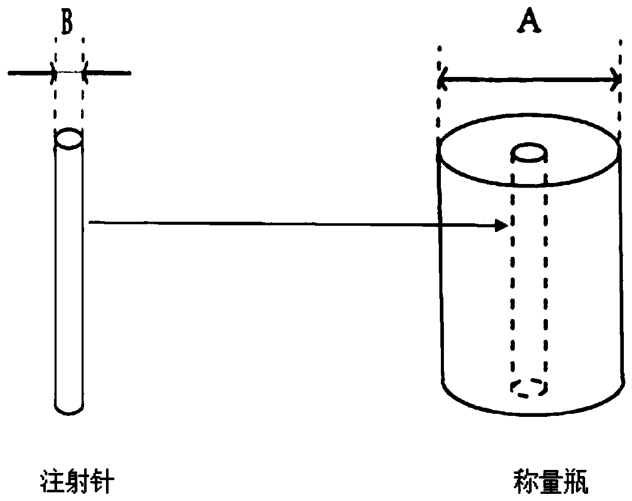
[0028] Figure 1-Figure 2 Medium, 1-vacuum degasser, 2-tested infusion pump, 3-pressure sensor, 4-damping tube, 5-high-pressure electric switching valve, 6-high precision timer, 7-waste liquid bottle, 8-high stability Weighing platform, 9-precision electronic balance, 10-windproof glass frame, 11-weighing bottle, 12-precision injection needle, 13-liquid paraffin.

[0029] In the present invention, the micro-flow and ultra-micro flow measurement devices include 1-vacuum degasser, which is used to remove dissolved gas in the liquid. At normal temperature, the gas has a cer...


PUM


Abstract

The invention discloses a microflow and ultramicro flow determination device. The device comprises a vacuum degasser, a determined infusion pump, a pressure sensor,a damping pipe and a high-pressure electric switching valve, wherein the high-pressure electric switching valve is communicated with the damping pipe, a high-precision timer, a waste liquid bottle and a precise injection needle separately; the precise injection needle goes deep into a weighing bottle; the weighing bottle is placed on a precise electronic scale and contains a determined liquid (pure water) and is sealed by liquid paraffin; the precise electronic scale is placed on a high-stability weighing platform. The problems about determination accuracy and precision of micro flow and ultramicro flow are solved, bubble removal means of the vacuum degasser and the damping pipe are introduced, a switching flowpath of the high-pressure electric switching valve is controlled through a switch of thehigh-precision timer, and influences caused by rising of the liquid level and buoyancy change are deducted during calculation, so that the flow can be accurately determined. The determination device has the advantages of being simple and rapid in determination, accurate and reliable in determination result and the like.

Description

technical field [0001] The invention relates to the technical field of liquid micro-flow and ultra-micro-flow measurement, and is particularly suitable for performance detection of ultra-micro-flow output equipment. Background technique [0002] At present, for the detection of micro-flow and ultra-micro-flow output devices, the mass method or the flow meter method is mainly used. The mass method uses pure water as the liquid medium to calculate the mass of pure water output by the liquid output device per unit time. The flowmeter method is to directly test the performance of the liquid output device through the flowmeter, but the flowmeter itself also needs to be calibrated by the mass method. [0003] At present, there is no perfect method for testing liquid micro-flow and ultra-micro-flow. There are certain problems in the determination of mass method, for example, it does not consider the problem of the buoyancy of the injection needle caused by the increase of the liq...

Claims


Application Information

Patent Timeline
Patent Type & Authority Applications(China)
IPC IPC(8): G01F11/28G01F11/00
CPCG01F11/006G01F11/28
Inventor 李明马昱周兴陈才陈锦峰
Owner SHANGHAI WUFENG SCI INSTR
Learn More