Cutter head protection device for numerically controlled machine tools

A technology of CNC machine tools and protective devices, applied in feeding devices, maintenance and safety accessories, metal processing machinery parts, etc., can solve problems such as tool damage, low efficiency, improper tool feeding, etc. Guaranteed effect

Active Publication Date: 2020-11-17
南通俊飞激光机械有限公司
View PDF8 Cites 0 Cited by
  • Summary
  • Abstract
  • Description
  • Claims
  • Application Information

AI Technical Summary

Problems solved by technology

[0003] Reference document CN104209990A mentions a tool protection type planer. The main problem to be solved is to protect the tool, and in the process of protection, it is convenient to adjust the position of the tool and adapt to different thicknesses of wool. However, CNC machine tools usually use The tool processes the parts. In the mechanical cutting process, it is inevitable that there will be mistakes in the operation process. The operator controls the tool feed improperly, the feed rate is too large or the feed speed is not well controlled, which will easily cause the tool head to damage the part. Collision will cause the tool to loosen and chip. In severe cases, it may cause accidents such as the tool or the workpiece flying out, causing damage to the tool and causing personal danger and injury to the operator. In addition, for tooth opening processing that requires a similar gear structure, it is necessary Repeated forward and backward feeding at the end, so frequent reverse operations are required, and the efficiency is low; in addition, although CN108113034A discloses a driving gear with two driven gears and an arc-shaped gear structure, the purpose is to realize the reciprocating movement of the glutinous rice cakes, but there is no Any questions about how to deal with fine stepping during reciprocating motion

Method used


Image

  • Cutter head protection device for numerically controlled machine tools
  • Cutter head protection device for numerically controlled machine tools
  • Cutter head protection device for numerically controlled machine tools

Examples


Embodiment Construction

[0023] The following will clearly and completely describe the technical solutions in the embodiments of the present invention with reference to the accompanying drawings in the embodiments of the present invention. Obviously, the described embodiments are only some, not all, embodiments of the present invention.

[0024] In describing the present invention, it should be understood that the terms "upper", "lower", "front", "rear", "left", "right", "top", "bottom", "inner", " The orientation or positional relationship indicated by "outside", etc. is based on the orientation or positional relationship shown in the drawings, and is only for the convenience of describing the present invention and simplifying the description, rather than indicating or implying that the referred device or element must have a specific orientation, so as to Specific orientation configurations and operations, therefore, are not to be construed as limitations on the invention.

[0025] refer to Figure ...


PUM


Abstract

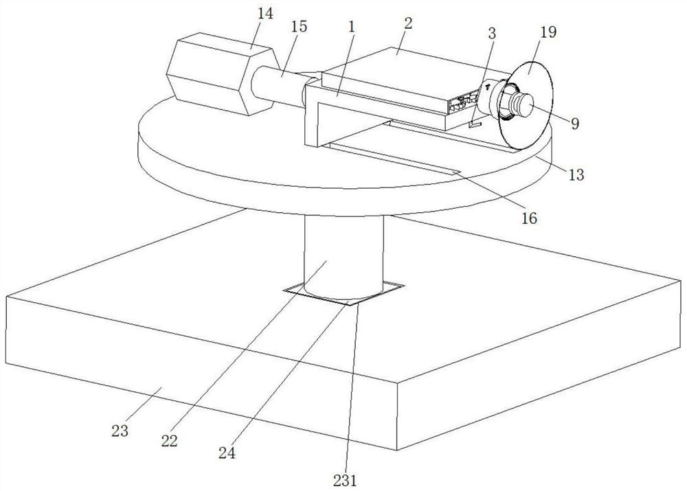
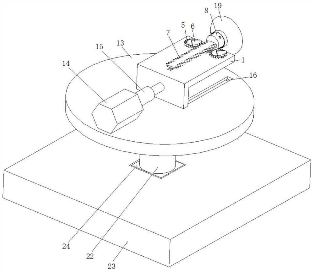
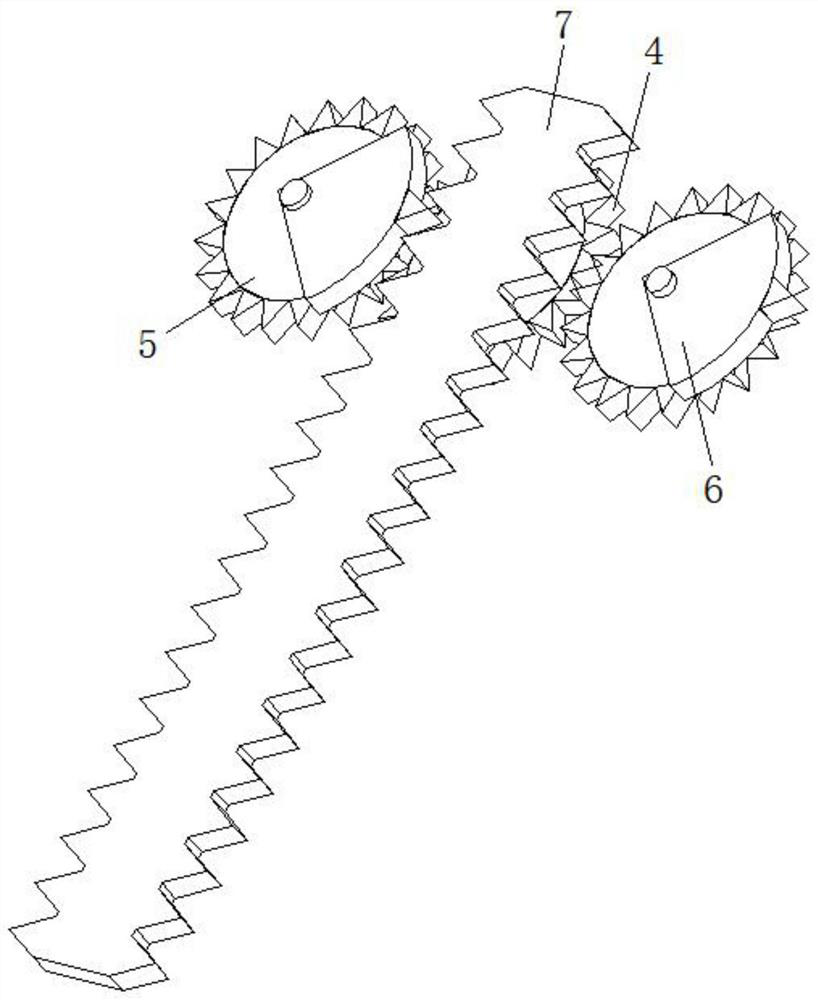
The invention discloses a tool bit protection device for a numerical control machine tool, and belongs to the technical field of tool bit protection. The tool bit protection device for the numerical control machine tool comprises a fixing plate, wherein the outer wall of the fixing plate is fixedly connected with a shell; the bottom of the fixing plate is fixedly connected with a handle, and the output end of the handle is fixedly connected with a rotating shaft; one end of the rotating shaft, which is far away from the handle, penetrates through the fixing plate and is fixedly connected witha main gear, and the outer walls of the two sides of the main gear are respectively connected with a pinion in a meshed manner; the main gear and the pinions are rotatably connected between the fixingplate and the inner wall of the shell, the tops of the two pinions are fixedly connected with sector gears, and a transmission rack is meshed and connected between the two sector gears; and the outerwall of the transmission rack is fixedly connected with a tool shell, and a tool is sleeved in the tool shell. According to the tool bit protection device for the numerical control machine tool, theextending distance of the tool bit is finely adjusted by controlling, so that the damage of the tool bit caused by too large feeding amount or poor feeding speed of the tool bit is avoided, and the protection of the tool bit is facilitated.

Description

technical field [0001] The invention relates to the technical field of cutter head protection, in particular to a cutter head protection device for a numerically controlled machine tool. Background technique [0002] CNC machine tool is the abbreviation of digital control machine tool. It is an automatic machine tool equipped with a program control system. It can make the machine tool move and process parts according to the programmed program. Technology, the basic composition includes processing program carrier, numerical control device, servo drive device, machine tool body and other auxiliary devices. CNC machine tool solves the problem of complex, precise, small batch and multi-variety parts processing. It is a flexible and high-efficiency machine tool. Automated machine tools represent the development direction of modern machine tool control technology and are a typical mechatronic product. [0003] Reference document CN104209990A mentions a tool protection type planer...

Claims


Application Information

Patent Timeline
Patent Type & Authority Patents(China)
IPC IPC(8): B23Q11/08B23Q5/22
CPCB23Q5/22B23Q11/08
Inventor 金美红
Owner 南通俊飞激光机械有限公司
Why Eureka
Try Eureka