Method for predicting and maintaining condensation performance of solar disc type condensation system

A technology of concentrating system and solar energy, applied in the field of solar concentrating utilization, can solve the problems of structural deformation, unbalanced solar radiation energy, deterioration of focusing performance and radiation energy flow distribution, etc.

Active Publication Date: 2019-11-12
HUNAN UNIV OF SCI & TECH
View PDF3 Cites 6 Cited by
  • Summary
  • Abstract
  • Description
  • Claims
  • Application Information

AI Technical Summary

Problems solved by technology

However, during the service period of the project, the dish concentrating system will be subjected to structural deformation due to its own weight and wind load, which will deteriorate its focusing performance and radiation energy flow distribution, and cause the solar radiation energy received by the surface of the Stirling heat engine heat sink to be insufficient. Balanced, reducing light-heat-work-electricity conversion efficiency, and more seriously, it will cause high-temperature hot spots on the heat absorber coil, resulting in safety problems such as ablation or burn-through
In particular, the more stringent requirements of commercial power stations are that the concentrating dish system should operate normally within a certain wind speed (usually 8-level wind), which brings more severe challenges to the safe and efficient operation of the concentrating dish system.

Method used


Image

  • Method for predicting and maintaining condensation performance of solar disc type condensation system
  • Method for predicting and maintaining condensation performance of solar disc type condensation system
  • Method for predicting and maintaining condensation performance of solar disc type condensation system

Examples


Embodiment Construction

[0079] The present invention will be further described below in conjunction with the accompanying drawings and embodiments.

[0080] The present invention comprises the steps:

[0081] Step 1: Establish the structural finite element model of the dish concentrating system, divide the structural finite element model of the dish concentrating system into grids, and output the spatial coordinate information of each grid node of the concentrator reflector under the non-loading condition , to calculate the optical information of the dish concentrator under the condition of no optical error and no loading condition. Its specific operation is as follows:

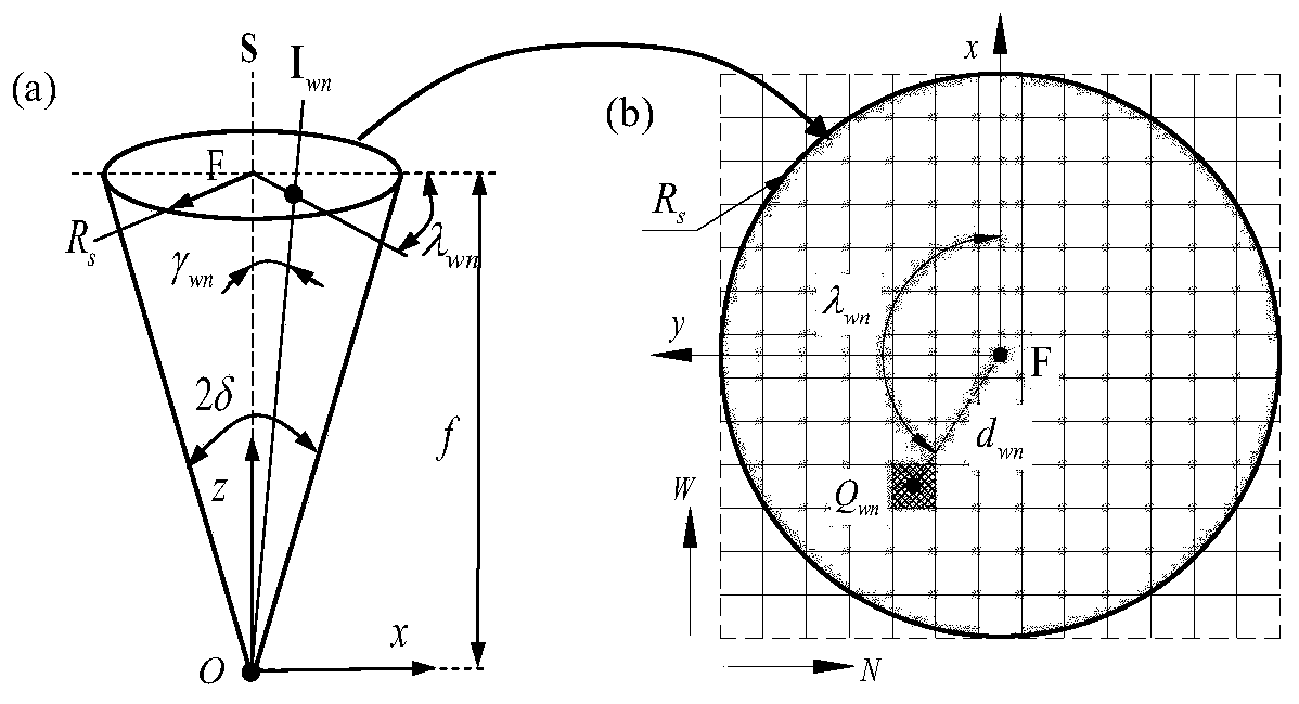
[0082] Step 1.1: Establish a global coordinate system for mechanical and optical analysis. The global coordinate system O-xyz is established at the vertex O position of the parabolic mirror of the dish concentrator, the z-axis points to the focus F of the parabolic surface, and the focus F position vector F=[0,0,f], f is the parab...


PUM


Abstract

The invention discloses a method for predicting and maintaining condensation performance of a solar disc type condensation system, and the method comprises the following steps: 1), building a finite element model of the disc type condensation system, and calculating the optical information of a disc type condenser under a non-bearing condition without an optical error; 2) calculating optical parameters of each plane infinitesimal grid of a condenser reflecting mirror surface when self-weight and wind pressure load boundary conditions are applied; 3) predicting the focusing energy flow distribution and the optical performance of the disc type condensation system under the action of the load by adopting a ray tracing method; 4) fitting to obtain a function model of the tracking error angle value and the centroid position of the focusing light spot; 5) determining the centroid position of the focusing light spot according to the operation condition, and reversely solving the output cornererror value of the double-axis tracking device; and rotating an output shaft of the double-shaft tracking device by a corresponding angle, so that the condensation performance of the disc type condensation system is kept. The method is easy to implement, the light condensation performance of the disc type light condensation system under the bearing working condition can be predicted, energy flowdistribution is kept, and the design of the disc type system is guided.

Description

technical field [0001] The invention belongs to the technical field of solar energy concentration utilization, and in particular relates to a method for predicting and maintaining the light concentration performance of a solar dish type concentration system. Background technique [0002] Solar energy is clean, environmentally friendly, abundantly supplied and widely distributed renewable energy. Concentrating solar thermal power generation is an important technology for the development and utilization of solar energy resources, and is considered to be an important way to solve the problems of energy shortage and environmental pollution. Dish-Stirling solar thermal power generation system uses a parabolic dish concentrator to gather sunlight to the surface of the metal coil in the receiver, and is used to heat the gas working fluid (usually hydrogen or helium) in the metal coil , and then the heated gas working medium will drive the Stirling heat engine to drive the generato...

Claims


Application Information

Patent Timeline
IPC IPC(8): G06F17/50F24S50/20
CPCF24S50/20Y02E10/47Y02E10/46
Inventor 颜健彭佑多
Owner HUNAN UNIV OF SCI & TECH
Why Eureka
Try Eureka