
Release agent automatic recovery energy saving equipment and treatment system thereof

A technology of energy-saving equipment and release agent, which is applied in the petroleum industry, lubricating composition, etc., can solve the problems of low quality of release agent treated products, inability to effectively separate, inconvenient maintenance and other problems, and achieves reduction of wax deposition and compact structure. , The beautiful effect of the equipment

Pending Publication Date: 2019-11-12
SUZHOU RES INST SHANDONG UNIV +1
View PDF5 Cites 0 Cited by
  • Summary
  • Abstract
  • Description
  • Claims
  • Application Information

AI Technical Summary

Problems solved by technology

[0002] The quality of the release agent processed products obtained by the traditional release agent recovery process equipment is low, the product quality is not high, and it is fundamentally impossible to effectively separate the release agent, realize the release agent sterilization, and prevent the release agent from waxing
Most of the existing equipment is split type, the structure is not compact enough, the floor area is large, the energy consumption is high, the fault maintenance is inconvenient, and it cannot meet the actual production needs

Method used


Image

  • Release agent automatic recovery energy saving equipment and treatment system thereof
  • Release agent automatic recovery energy saving equipment and treatment system thereof
  • Release agent automatic recovery energy saving equipment and treatment system thereof

Examples


Embodiment Construction

[0026] The specific embodiments of the present invention will be further described below in conjunction with the accompanying drawings. It should be noted here that the descriptions of these embodiments are used to help understand the present invention, but are not intended to limit the present invention. In addition, the technical features involved in the various embodiments of the present invention described below may be combined with each other as long as they do not constitute a conflict with each other.

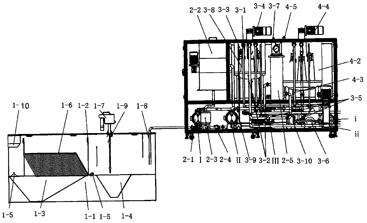
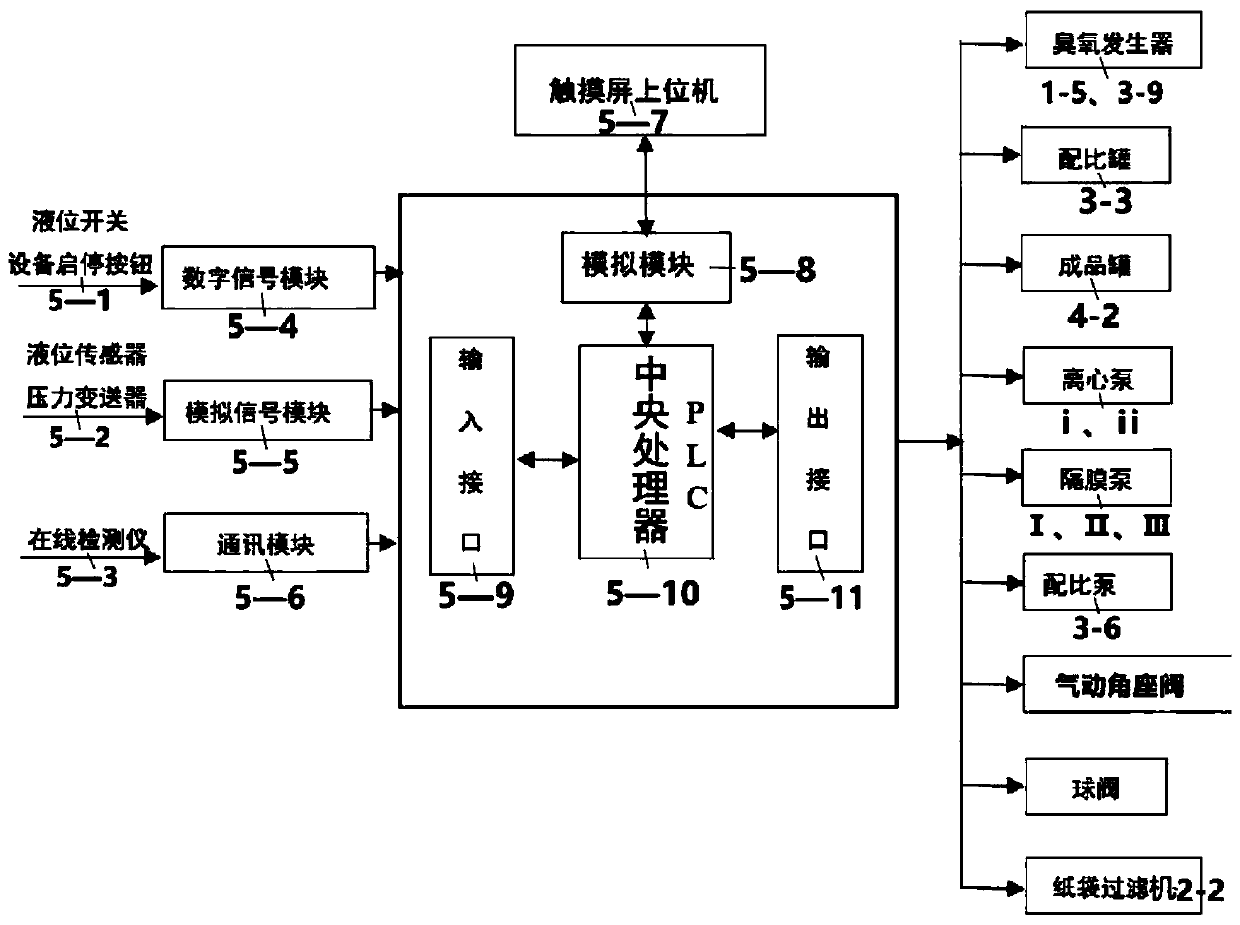
[0027] Such as Figure 1-3 As shown, the release agent automatic recycling energy-saving equipment and its processing system in this embodiment include a pre-processing device 1 for the release agent, a post-processing device 2, a proportioning collection device 3 and a finished product storage device 4, wherein the former The processing device 1 is located under the cutting machine table and connected to the post-processing device 2, the post-processing device 2 is con...


PUM


Abstract

The invention discloses release agent automatic recovery energy saving equipment and a treatment system thereof. The release agent automatic recovery energy saving equipment comprises a pre-treatmentdevice, a post-treatment device, a proportioning collection device and a finished product storage device, wherein the pre-treatment device, the post-treatment device, the proportioning collection device and the finished product storage device are used for a release agent. According to the release agent automatic recovery energy saving equipment and the treatment system thereof, a circular tank structure is adopted, bacteria are not prone to breeding, and cleaning is convenient; an inclined tube sedimentation tank is adopted, the precipitation efficiency is high, and the effect is good; demoulding agent waste liquid passes through a magnetizer to reduce the waxing phenomenon; a remote transmission control function is used for detecting the state of the equipment in real time; a whole structure is adopted, the structure is compact, the occupation area is small, and the equipment is attractive; the recovery and reuse of the release agent waste liquid is achieved, and the release agent waste liquid can further be mixed with a novel release agent for using; a machine unit is fully automatically operated, safety and reliablity are achieved, and the maintenance and use are simpler; core components are imported, the failure rate is lower, and the product service cycle is longer; real-time monitoring is proportioned, and the automatic proportioning can be adjusted; and big data record is used, convenient use is achieved, the cost is reliable, so that higher operation efficiency is obtained.

Description

technical field [0001] The invention relates to a release agent recycling device, in particular to an automatic release agent recycling energy-saving device and a processing system thereof, which are used to solve the problem of low recovery efficiency of release agent waste liquid. Background technique [0002] The quality of the treated product of the release agent obtained by the traditional release agent recovery process equipment is low, the product quality is not high, and it is fundamentally impossible to effectively separate the release agent to achieve the sterilization of the release agent and prevent the release agent from waxing. Most of the existing equipment is of split type, not compact enough in structure, large in floor area, high in energy consumption, inconvenient in fault maintenance, and unable to meet actual production needs. Contents of the invention [0003] In view of the problems existing in the above-mentioned background technology, the object of...

Claims


Application Information

Patent Timeline
Patent Type & Authority Applications(China)
IPC IPC(8): C10M175/00C10M177/00
CPCC10M175/00C10M175/0016C10M175/0066C10M177/00C10N2040/36
Inventor 吕明新方志杰郝立群王金坤董震吴艳章赵越
Owner SUZHOU RES INST SHANDONG UNIV
Learn More