
Bionic flexible morphing wing

A wing and flexible technology, applied in the field of deformable UAV structure, can solve the problems of energy waste, environmental pollution, reduce the service life of the aircraft, increase the flight resistance of the aircraft, and achieve the reduction of maintenance difficulty and cost, aerodynamics Excellent performance, reduced drag and noise

Pending Publication Date: 2019-11-12
JILIN UNIV
View PDF0 Cites 4 Cited by
  • Summary
  • Abstract
  • Description
  • Claims
  • Application Information

AI Technical Summary

Problems solved by technology

In order to realize the change of the aircraft's flight attitude, the traditional wing requires various front and rear edge lift devices, ailerons, spoilers, speed brakes, elevons and other mechanisms on the movable wing surface. The components of the wing rely on traditional mechanical transmission. way to control the working state of the wing, the structure is complex
At the same time, the traditional wing will produce greater vibration noise and greater flight resistance during ultra-high-speed flight, which reduces the service life of the aircraft
And the increase of the wing function will inevitably increase the number of wing components, increase the weight of the aircraft, increase the flight resistance of the aircraft on the other hand, cause energy waste and environmental pollution, and increase the manufacturing cost of the aircraft
On some small fixed-wing UAVs, in order to reduce the difficulty of manufacturing, the wing is usually designed as a fixed device. Although this can reduce the difficulty of manufacturing the aircraft, the performance of the aircraft is limited and cannot achieve a certain purpose of flight.
[0003] With the development of the aviation industry, people require aircraft to have better flight performance and handling performance. It is difficult to achieve technological breakthroughs in the performance of traditional wings, which limits the improvement of aircraft performance to a large extent.

Method used


Image

  • Bionic flexible morphing wing
  • Bionic flexible morphing wing
  • Bionic flexible morphing wing

Examples


Embodiment Construction

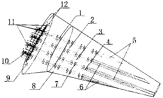
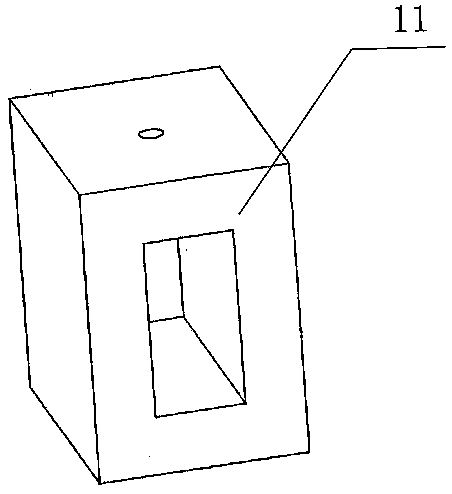
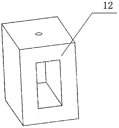
[0038] see figure 1 , figure 2 , image 3 , Figure 4 , Figure 5 and Figure 6 As shown, the present invention includes a first transverse framework 1, a second transverse framework 2, a third transverse framework 3, a fourth transverse framework 4, a group A longitudinal framework 5, a B group longitudinal framework 6, a heat insulating layer 7, and a wing covering Skin 8, connecting device 9, fixing device 10, group A temperature control system 11, group B temperature control system 12;

[0039] The first transverse framework 1, the second transverse framework 2, the third transverse framework 3 and the fourth transverse framework 4 are distributed at intervals from the inside to the outside, the longitudinal frameworks 5 of group A and the longitudinal frameworks 6 of group B are distributed at intervals, the longitudinal frameworks of group A 5 and Group B’s longitudinal skeletons 6 all fit together through the first transverse skeleton 1, the second transverse skel...


PUM


Abstract

A bionic flexible morphing wing comprises a wing framework, a wing skin, a heat insulation layer, a fixing device, a temperature control system and a connecting device; and the framework comprises a transverse framework and a longitudinal framework. The wing skin is integrally molded and bonded on the wing framework by using an adhesive. The longitudinal framework is made of a shape memory alloy;and the embedded part of the transverse framework and the longitudinal framework are heat-insulated by using the heat insulation layer. The longitudinal framework adopts the shape memory alloy; different shape memories are trained for each group of shape memory alloys; and active driving morphing after given shaping can be realized under electrothermal excitation. In the flying process, a temperature control system adjusts the temperature of the longitudinal framework, controls the two groups of shape memory alloys with different parameters to correspondingly generate upward morphing or downward morphing, and the wing is driven to morph upwards or downwards to achieve the flying purpose. According to the bionic flexible morphing wing, the wing can morph upwards or downwards under a condition without a power device, the wing structure is simplified, the weight of the wing is reduced, and the flying performance of an aircraft is improved.

Description

technical field [0001] The invention belongs to the field of deformable unmanned aerial vehicle structures, and relates to a bionic flexible deformable wing. Background technique [0002] Since the 1880s, research on wing structures has been extensively carried out by many teams around the world. From the initial concept of hingeless bending, it has been developed to the study of large-scale deformation of aircraft. The main function of the wing is to generate lift to support the flight of the aircraft in the air, and it also plays a certain role in stability and control. Traditional fixed-wing aircraft rely on the movement of the leading edge and trailing edge of the wing to control the distribution of lift or drag of the wing, so as to increase lift or change the flight attitude of the aircraft. In order to realize the change of the aircraft's flight attitude, the traditional wing requires various front and rear edge lift devices, ailerons, spoilers, speed brakes, elevon...

Claims


Application Information

Patent Timeline
IPC IPC(8): B64C3/38
CPCB64C3/38
Inventor 张志辉张晓龙刘庆萍于征磊刘宇霆邵艳龙张清泉
Owner JILIN UNIV
Learn More