Fire protection system for belt conveyor

A belt conveyor and belt technology, which is applied to conveyor objects, conveyor control devices, applications, etc., can solve the problems of belt conveyors that do not have both cooling treatment methods, small collection surfaces, and local overheating, etc., to ensure comprehensive performance and effectiveness, avoiding the effects of small collection area and fast collection efficiency

Pending Publication Date: 2019-11-08
山东英发信息科技有限公司
View PDF0 Cites 1 Cited by
  • Summary
  • Abstract
  • Description
  • Claims
  • Application Information

AI Technical Summary

Problems solved by technology

[0002] The belt conveyor has the advantages of large conveying capacity, simple structure, convenient maintenance, and standardized components. It is widely used in mining, metallurgy, coal and other industries to convey loose materials or finished items. According to the requirements of the conveying process, it can be conveyed by a single It can also be composed of multiple sets or combined with other conveying equipment to form a horizontal or inclined conveying system. The existing technology cannot measure the temperature of moving target objects or the difficulties in engineering practice cannot be overcome. Therefore, the temperature of stationary parts can only be measured indirectly. , while the traditional belt conveyor is used for a long time, it is very easy to cause fire due to local overheating
[0003] The traditional device has the following disadvantages: the traditional belt conveyor is prone to fire caused by local overheating during long-term use. At the same time, most of the existing detection components use point-to-point detection. The disadvantages of small size and large limitations, and most of the existing belt conveyors do not have cooling treatment methods, so it is impossible to carry out comprehensive protection treatment for belt conveyors

Method used


Image

  • Fire protection system for belt conveyor
  • Fire protection system for belt conveyor
  • Fire protection system for belt conveyor

Examples


Embodiment Construction

[0029] The following will clearly and completely describe the technical solutions in the embodiments of the present invention with reference to the drawings in the embodiments of the present invention.

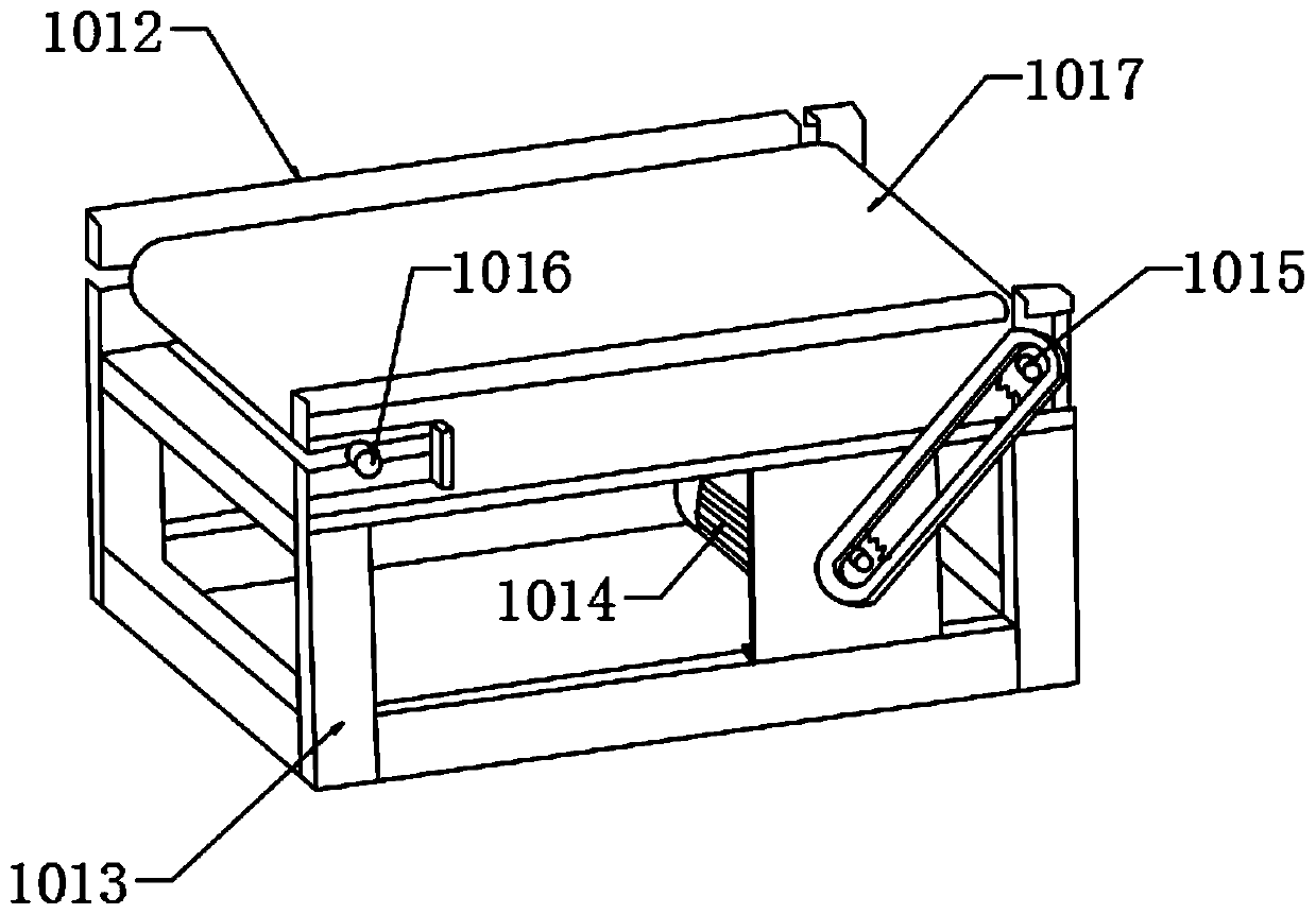
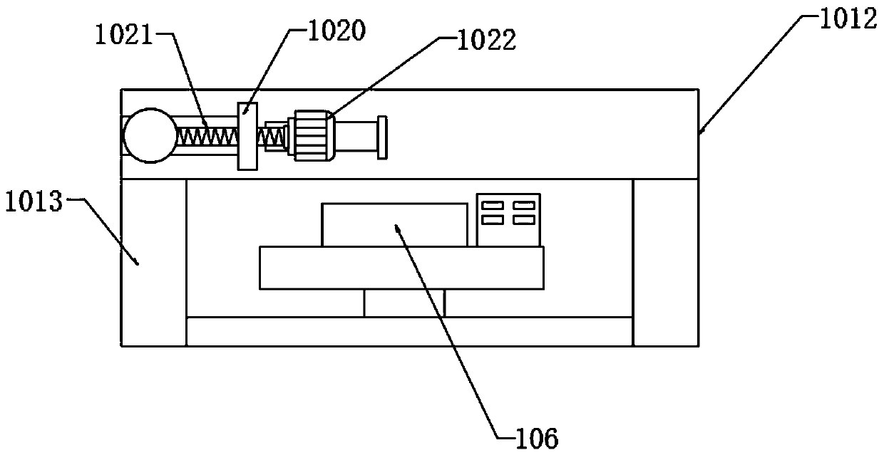
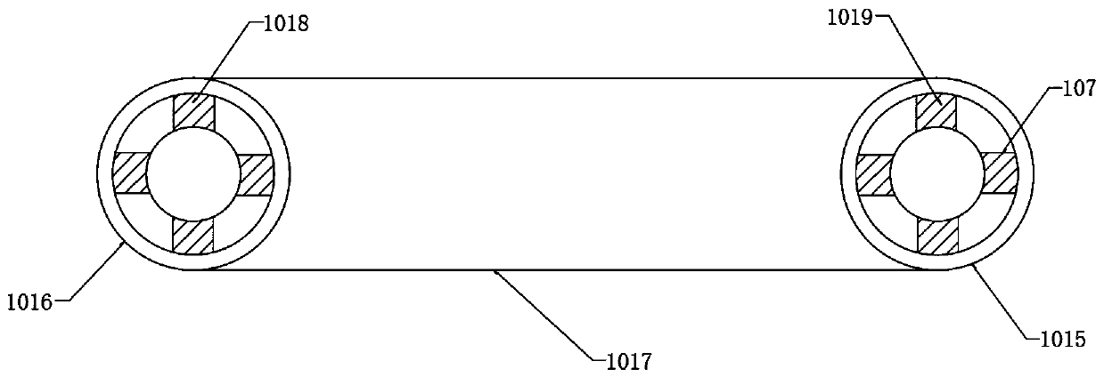
[0030] see Figure 1-6 , the present invention provides a technical solution: a fire protection system for belt conveyors, comprising:

[0031] Collection terminal 101, application platform 102, described collection terminal 101 and application platform 102 are connected through data transmission module 103;

[0032] A collection terminal 101, the collection terminal 101 is composed of a detector 104, a processing mechanism 105, and a detection unit 107, the detector 104 includes a temperature detection module and a data conversion module, and the detector 104 is electrically connected to the detection unit 107, The detector 104 adopts a thermal imager, a radiation thermometer or other bolometric temperature measuring instruments;

[0033] Application platform 102, described...


PUM

PropertyMeasurementUnit
Angleaaaaaaaaaa

Abstract

The invention discloses a fire protection system for a belt conveyor. The fire protection system comprises a collection terminal and an application platform, wherein the collection terminal and the application platform are connected through a data transmission module; the collection terminal is composed of a detector, a processing mechanism and a detection unit; the detector comprises a temperature detecting module and a data conversion module; the detector is electrically connected with the detection unit; and the application platform comprises a processing module, an image display module andan alarm module. By arranging the detecting unit, omnidirectional detection operation on the temperature of a belt conveyor belt main body can be conducted rapidly, the normal use state of the belt conveyor belt main body is ensured, by arranging the processing mechanism, the belt conveyor belt main body can be effectively cooled in an assisted mode, then the belt conveyor belt main body is protected thoroughly, when the temperature of the belt conveyor belt reaches a limit value, the belt conveyor belt can be driven to stop in time, and thus the overall application safety is improved.

Description

technical field [0001] The invention relates to the technical field of belt conveyor equipment, in particular to a fire prevention system for belt conveyors. Background technique [0002] The belt conveyor has the advantages of large conveying capacity, simple structure, convenient maintenance, and standardized components. It is widely used in mining, metallurgy, coal and other industries to convey loose materials or finished items. According to the requirements of the conveying process, it can be conveyed by a single It can also be composed of multiple sets or combined with other conveying equipment to form a horizontal or inclined conveying system. The existing technology cannot measure the temperature of moving target objects or the difficulties in engineering practice cannot be overcome. Therefore, the temperature of stationary parts can only be measured indirectly. , At the same time, when the traditional belt conveyor is used for a long time, it is very easy to cause a...

Claims


Application Information

Patent Timeline
IPC IPC(8): B65G43/02F25D1/02
CPCB65G43/02F25D1/02
Inventor 刘毅
Owner 山东英发信息科技有限公司
Why Eureka
Try Eureka