
Anti-falling bolt and nut for electric power iron tower and working method thereof

A power tower, bolt and nut technology, applied in the direction of nuts, bolts, screws, etc., can solve the problems of falling off, loose bolts and nuts, hidden dangers, etc., and achieve the effect of preventing falling off

Active Publication Date: 2019-11-05
STATE GRID CORP OF CHINA +1
View PDF7 Cites 3 Cited by
  • Summary
  • Abstract
  • Description
  • Claims
  • Application Information

AI Technical Summary

Problems solved by technology

[0003] 1. In the case of strong wind, the overall swing of the power tower will be caused, and the bolts and nuts will loosen and fall off during the swing process, resulting in potential safety hazards;
[0004] 2. In addition to tools and bolts and nuts, operators also need to prepare corresponding washers (flat washers, spring washers) or snap rings during the construction process. Due to the large number of washers or snap rings, it is inconvenient to take them when using them. If it is taken, it will increase the load of construction personnel and increase the construction risk of high-altitude operations

Method used


Image

  • Anti-falling bolt and nut for electric power iron tower and working method thereof
  • Anti-falling bolt and nut for electric power iron tower and working method thereof
  • Anti-falling bolt and nut for electric power iron tower and working method thereof

Examples


Embodiment Construction

[0057] In order to more clearly and clearly illustrate the specific implementation objectives and implementation modes of the present invention, the technical solution of the present invention will be fully described below, and the described embodiments are part of the embodiments of the present invention, rather than all embodiments. On the premise of no creative work, all other embodiments based on the described embodiments of the present invention belong to the protection scope of the present invention.

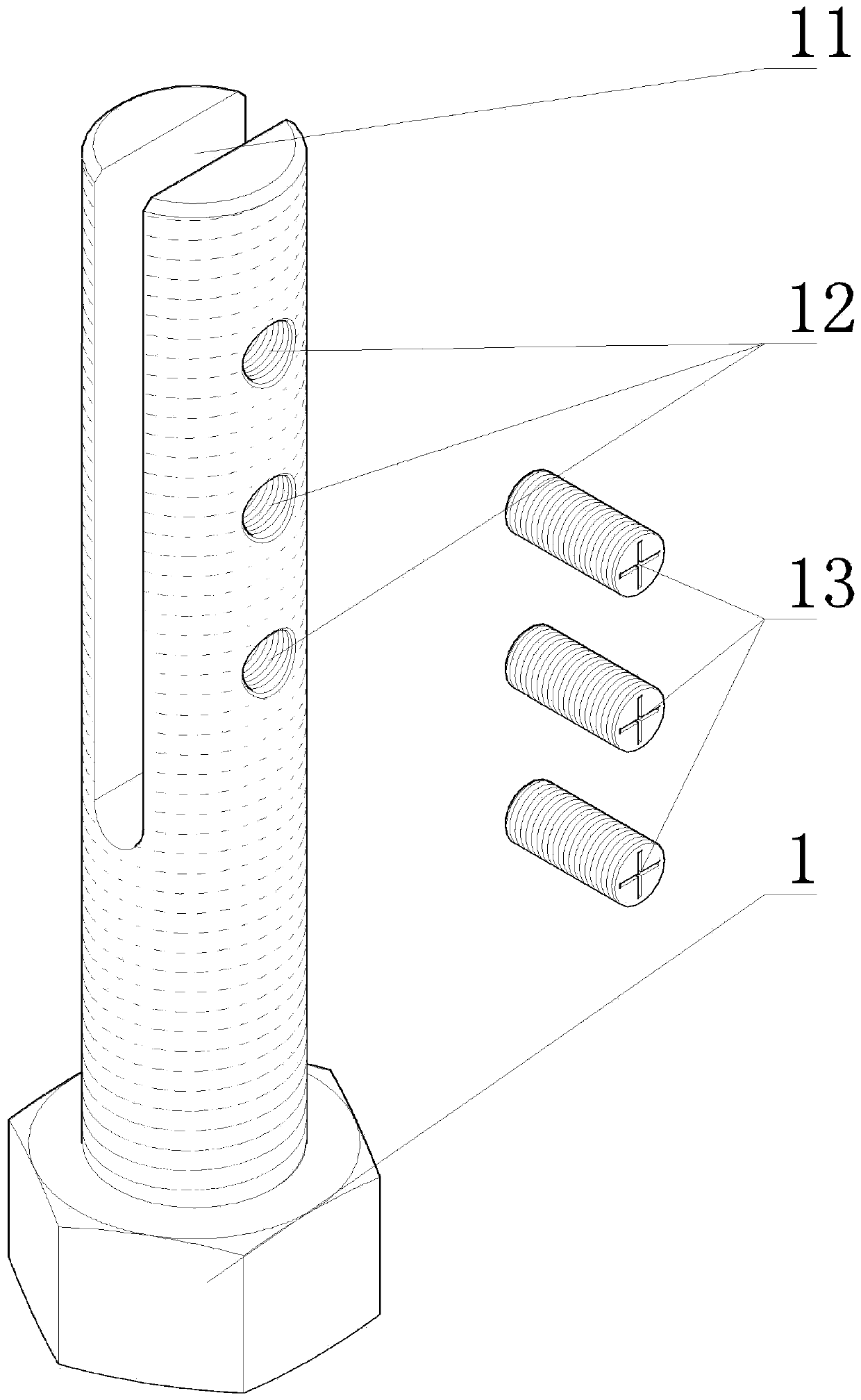
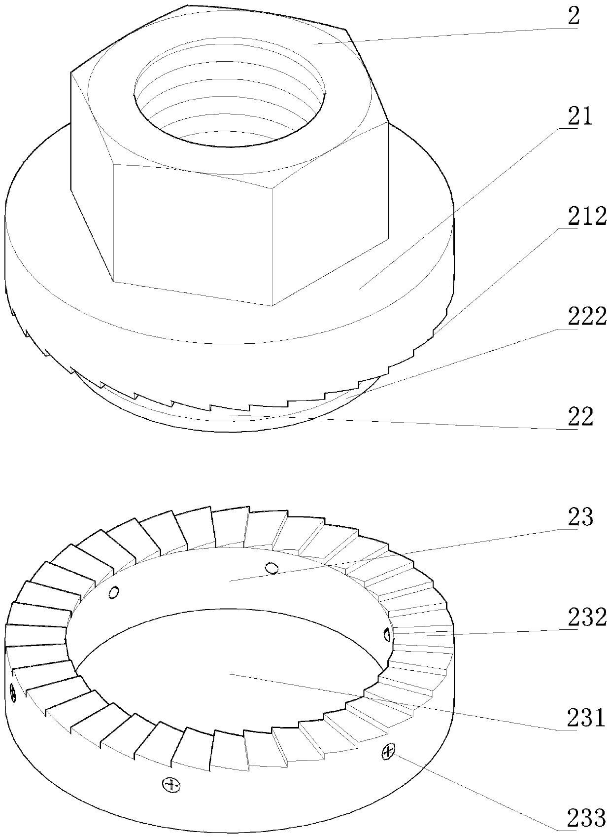
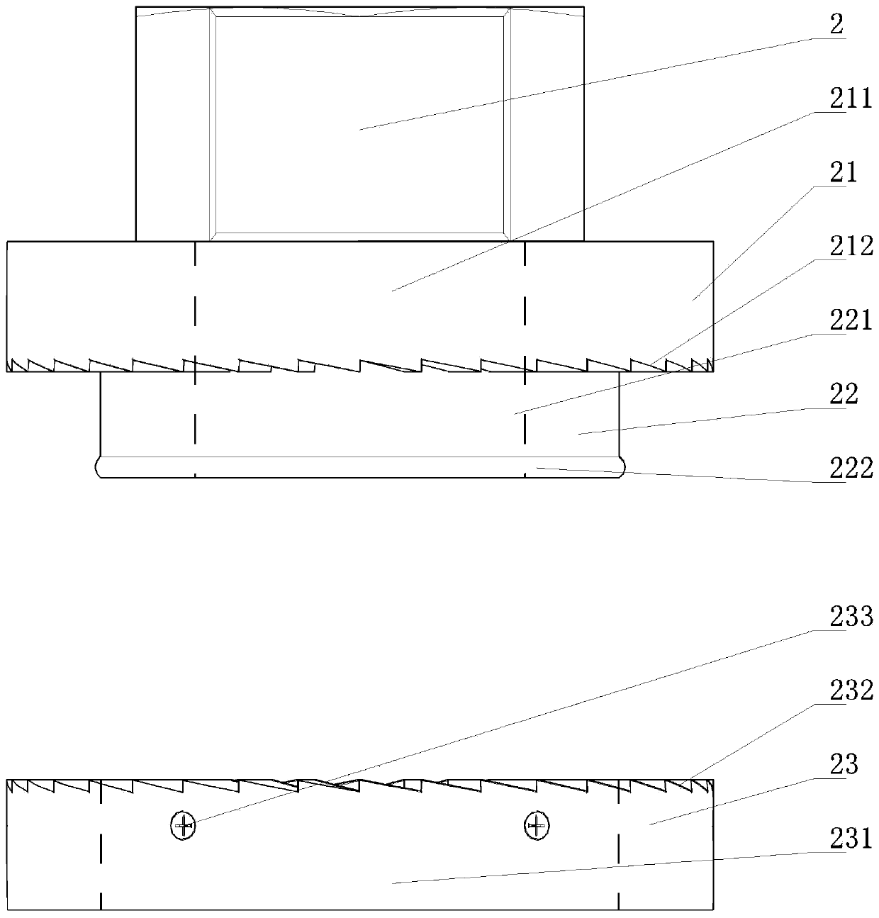
[0058] An anti-falling bolt and nut for an electric power tower of the present invention comprises a bolt 1 and a nut 2:

[0059] Such as figure 1 As shown, the screw rod of the bolt 1 is provided with a groove 11 through its central axis, so that the screw rod of the bolt 1 forms a "U"-shaped structure, and the bolt 1 on the side of the groove 11 is provided with a plurality of screw holes. The hole 12 is screwed with a limit screw 13 inside the screw hole 12, and the limi...


PUM


Abstract

The invention relates to an anti-falling bolt and nut for an electric power iron tower and a working method thereof. The anti-falling bolt and nut comprises a bolt and a nut, wherein a penetrating groove enabling the bolt to form a U-shaped structure is formed in a screw rod of the bolt, a plurality of screw holes are formed in the positions, on one side of the penetrating groove, of the bolt in apenetrating mode, limiting screws are arranged in the screw holes in a threaded mode, one end of the nut is sequentially and fixedly provided with a pressing ring comprising a first penetrating hoe and a first ratchet wheel, and a sliding rod comprising a second penetrating hole and a boss, a sliding sleeve sleeves the sliding rod comprising a third penetrating hole and a first inserting hole, asecond inserting hole and inner threads are arranged at the inner end and the outer end of the first inserting hole respectively, a buckling part is arranged in the first inserting hole, and the buckling part comprises a jacking head, a push spring and a fixing screw. According to the anti-falling bolt and nut for the electric iron tower and the working method thereof, the situation that the boltand nut falls off due to looseness is prevented, the anti-falling bolt and nut only comprises two components of the bolt and the nut, so that the anti-falling bolt and nut is convenient to carry, take, mount and dismount.

Description

technical field [0001] The invention relates to the technical field of electric power tower installation, in particular to an anti-falling bolt and nut for a power tower and a working method thereof. Background technique [0002] Transmission line tower, referred to as power tower, is a tower-shaped building for power transmission. The characteristics of its tower-type space truss structure are: light weight, convenient transportation, convenient erection, convenient dismantling; windproof, rainproof, moisture-proof, anti-corrosion, lightning-proof effect is good. The rods of the space truss structure are mainly composed of a single equal-sided angle steel or a combined angle steel. The material of the angle steel is generally Q235 (A3F) and Q345 (16Mn). connect. Due to the characteristics of transmission lines, power towers are mostly built in mountainous areas, wilderness and other uninhabited wild areas. The natural environment in this area is harsh, and the installatio...

Claims


Application Information

Patent Timeline
IPC IPC(8): F16B39/32F16B39/04F16B35/04F16B37/00
CPCF16B35/041F16B37/00F16B39/04F16B39/32
Inventor 李军王辉尚建华范少华赵朋昌刘坤曹轶柳晓董梁李婷婷
Owner STATE GRID CORP OF CHINA
Learn More