Sputtering film-forming device
A film forming device and sputtering technology, which is applied in sputtering plating, ion implantation plating, metal material coating process, etc., can solve the problem that the rotation speed ratio of the substrate tray cannot be adjusted freely, and the vacuum side gear transmission is easy to generate dust. , can not meet the needs of high-quality coating and other problems, to achieve the effect of meeting high precision and low defects, reducing dust, and reducing the generation of substrate film defects
- Summary
- Abstract
- Description
- Claims
- Application Information
AI Technical Summary
Problems solved by technology
Method used
Image

Examples
Embodiment 1
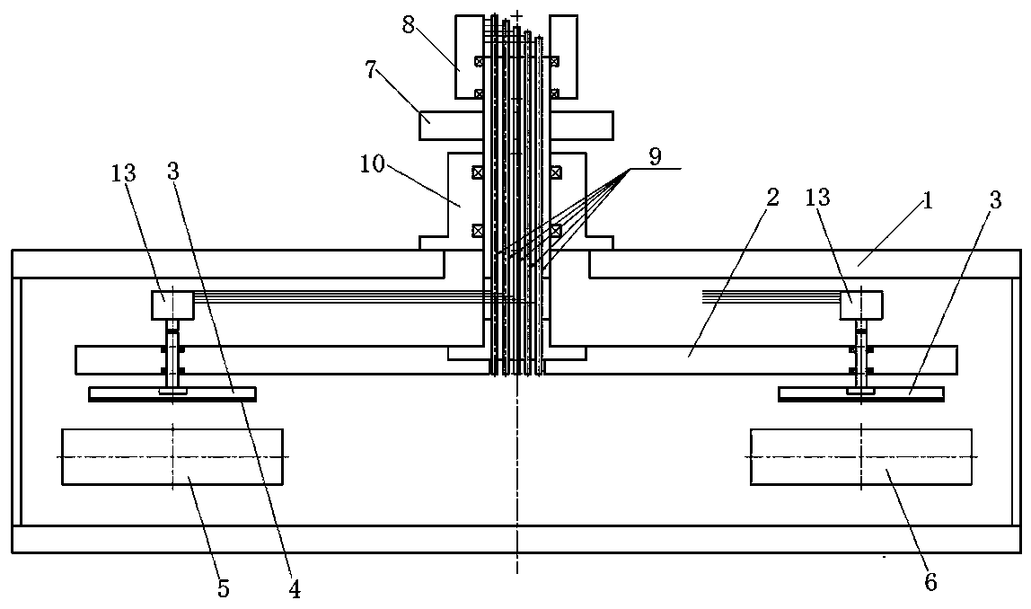
[0018] Example 1: The sputtering method usually uses metal mode sputtering to prepare optical films. The preparation method is that when the substrate tray (workpiece disk) rotates to the sputtering unit, the substrate deposits the target material film, and when the substrate tray rotates to the reaction unit , the target material film deposited on the surface of the substrate reacts to form an optical film. Such as figure 1 As shown, the main body of the sputtering film forming apparatus in this embodiment is a vacuum film forming chamber 1, and its interior is used as a film forming space, including a substrate tray revolution turntable 2 and a substrate tray autorotation turntable 3, wherein the substrate tray is The turntable 2 can revolve in the vacuum film forming chamber 1 , and the substrate tray rotation turntable 3 is connected below the substrate tray revolution turntable 2 and can rotate in the vacuum film forming chamber 1 . Substrates 4 placed horizontally are r...
Embodiment 2
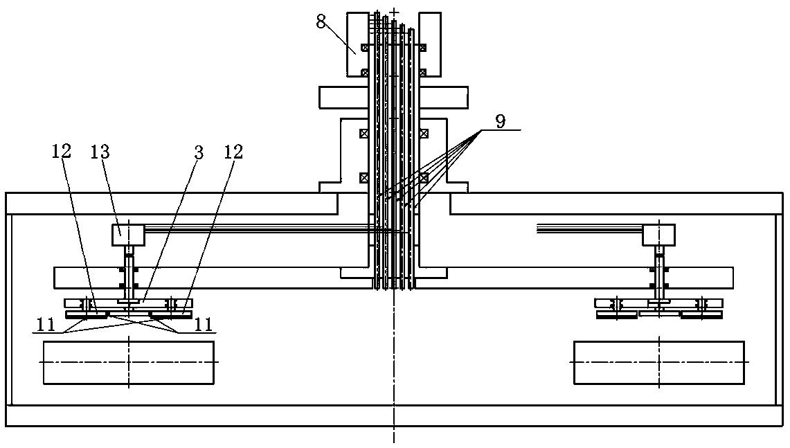
[0023] Embodiment two: if figure 2 As shown, the difference between this embodiment and the first embodiment is that a multi-stage sub-turntable structure is provided under the substrate tray autorotation turntable 3, and the multi-stage sub-turntable structure includes a plurality of sub-turntables 12. The number of turntables 12 can be selected according to the actual situation, but generally the sub-turntables 12 are symmetrically arranged around the rotation axis of the substrate tray rotation turntable 3 to ensure the uniformity of film thickness. The sub-turntable 12 is connected with a non-contact magnetic transmission part 11, the non-contact magnetic transmission part 11 can be adapted to the rotation shaft of the substrate tray autorotation turntable 3, and its function is to transmit the rotation of the rotation shaft of the substrate tray autorotation turntable 3 to the sub-turntable 12, so that each independent sub-turntable 3 can rotate independently under the s...
Embodiment 3
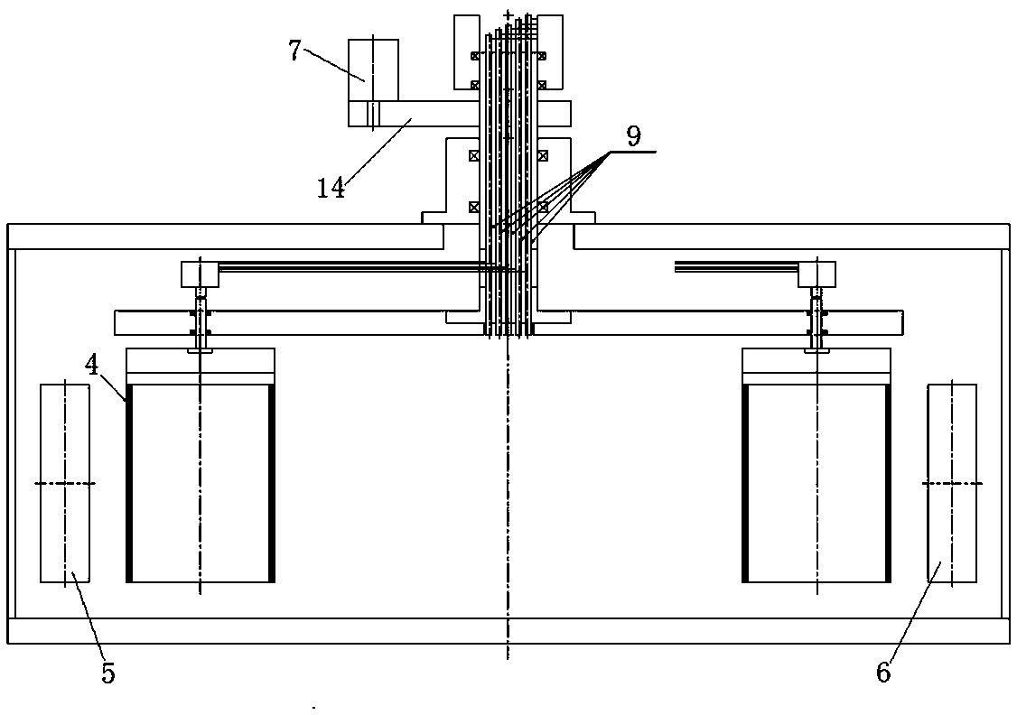
[0024] Embodiment three: as image 3 As shown, the difference between this embodiment and the first embodiment is that the vertically arranged substrate 4 is loaded under the substrate tray autorotation turntable 3, and the substrate 4 is arranged in the vacuum film forming chamber 1. The positions of sputtering unit 5 and reaction unit 6 are adapted. In combination with Embodiment 1, different loading modes can be selected according to different substrate sizes to meet the film-forming requirements of different substrates.
[0025] At the same time, another difference between this embodiment and the first embodiment is that the revolution motor 7 transmits its power to the rotating shaft of the substrate tray revolution turntable 2 through the transmission mechanism 14, so that the revolution motor 7 can be adjusted later. Carry out maintenance.
[0026] When the above-mentioned embodiment is actually implemented: the conductive slip ring 8 may be composed of rotating elect...
PUM
 Abstract
Description
Claims
Application Information
 - R&D
- Intellectual Property
- Life Sciences
- Materials
- Tech Scout
- Unparalleled Data Quality
- Higher Quality Content
- 60% Fewer Hallucinations
Browse by: Latest US Patents, China's latest patents, Technical Efficacy Thesaurus, Application Domain, Technology Topic, Popular Technical Reports.
© 2025 PatSnap. All rights reserved.Legal|Privacy policy|Modern Slavery Act Transparency Statement|Sitemap|About US| Contact US: help@patsnap.com