


Quick Research
Generate reliable direction feasibility study reports for your R&D in just a few steps.

Technical Q&A
Discover and master advanced knowledge NOW. Basics, ideas, possibilities, all at once.

Find Solutions
As an expert in R&D theories, this can generate solutions to your technical problems instantly.

Evaluate Feasibility
Analyze your overall solution with one click, know your potential R&D risks in advance.

Monitor Landscape
Get weekly tech updates, stay abreast of the latest tech innovations and key insights.
U-shaped thin-wall steel-prestress concrete combined bent cap and thin-wall steel tube concrete pier node structure and construction process
A thin-walled steel pipe and concrete pier technology, which is applied in bridges, bridge materials, bridge construction, etc., can solve the problems of large component cross-section, multiple reinforcements, and insufficient seismic performance, so as to achieve strong integrity, reliable force transmission, and ensure stability The effect of sex and construction accuracy
- Summary
- Abstract
- Description
- Claims
- Application Information
AI Technical Summary
Problems solved by technology
Method used
Image


Examples
Embodiment 1
[0046] This embodiment discloses a joint structure of a U-shaped thin-walled steel-prestressed concrete composite cover beam and a thin-walled concrete-filled steel pipe pier column, including a U-shaped thin-walled steel-prestressed concrete composite cover beam and a thin-walled steel pipe concrete pier column 7 .
[0047] see Figure 9 Or 10, the upper end of the thin-walled concrete-filled steel pipe pier 7 is connected to the lower surface of the mid-span of the U-shaped thin-walled steel-prestressed concrete composite cover beam.
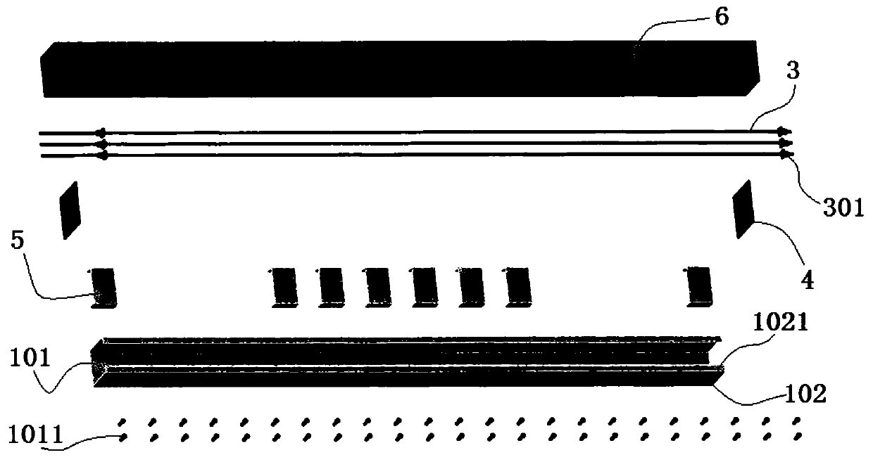
[0048] The U-shaped thin-walled steel-prestressed concrete composite cover beam includes U-shaped thin-walled steel plates 1 and several prestressed tendons 3 .
[0049] The U-shaped thin-walled steel plate 1 is processed by welding the thin-walled steel plate, and the processing process ensures equal strength welding. The model of the thin-walled steel plate is Q235. see figure 1 Or 2, the U-shaped thin-walled steel plate 1 is a constant-s...
Embodiment 2
[0064] This embodiment discloses a joint structure of a U-shaped thin-walled steel-prestressed concrete composite cover beam and a thin-walled concrete-filled steel pipe pier column, including a U-shaped thin-walled steel-prestressed concrete composite cover beam and a thin-walled steel pipe concrete pier column 7 .
[0065] see Figure 9 Or 10, the upper end of the thin-walled concrete-filled steel pipe pier 7 is connected to the lower surface of the mid-span of the U-shaped thin-walled steel-prestressed concrete composite cover beam.
[0066] The U-shaped thin-walled steel-prestressed concrete composite cover beam includes U-shaped thin-walled steel plates 1 and several prestressed tendons 3 .
[0067] see figure 1 , the cross-section of the U-shaped thin-walled steel plate 1 is U-shaped, with an opening at the upper end and a closed bottom at the lower end.
[0068] Below the opening is the inner cavity of the U-shaped thin-walled steel plate 1 .
[0069] The transverse ...
Embodiment 3
[0075] The main structure of this embodiment is the same as that of Embodiment 2, further, refer to figure 1 , 6 , 7 or 8, a number of pegs 1011 are welded on the upper surface of the bottom plate 101 .
PUM
 Abstract
Description
Claims
Application Information
 - R&D Engineer
- R&D Manager
- IP Professional
- Industry Leading Data Capabilities
- Powerful AI technology
- Patent DNA Extraction
Browse by: Latest US Patents, China's latest patents, Technical Efficacy Thesaurus, Application Domain, Technology Topic, Popular Technical Reports.
© 2024 PatSnap. All rights reserved.Legal|Privacy policy|Modern Slavery Act Transparency Statement|Sitemap|About US| Contact US: help@patsnap.com