
Pneumatic spring device for a rail vehicle

a technology for pneumatic springs and rail vehicles, which is applied in the direction of springs, vibration dampers, gas based dampers, etc., can solve the problems of high production costs, severe wear of pneumatic springs, and reinforcements may also be damaged, so as to achieve reliable operation, simple manner, and free from wear

Active Publication Date: 2014-11-11
CONTITECH LUFTFEDERSYST
View PDF18 Cites 0 Cited by
  • Summary
  • Abstract
  • Description
  • Claims
  • Application Information

AI Technical Summary

Benefits of technology

The invention provides a pneumatic spring device for rail vehicles that is reliable and durable even under high loads and severe movements. It is simple and can be produced without additional machining work. The device uses a bead ring with reinforcement elements that loop around the bead ring in an S-configuration, allowing for reliable embedding and force transmission with minimal damage to the reinforcement elements. This design also minimizes frictional wear in the contact region between the pneumatic spring and stop ring / flange. Furthermore, the S-shaped looping around the core rings is achieved by pulling them together, resulting in increased force transmission and reliable clamping of the reinforcement elements.

Problems solved by technology

One problem of fastening or clamping the pneumatic spring bellows to the stop rings or flanges of the chassis or of the subframe consists in the absorbing of the relatively heavily pronounced movements of a pneumatic spring system of this type.
These result in relative movements, which may cause severe wear of the pneumatic springs, in the region of the clamping points.
This in particular has disadvantages if the reinforcing fabric, that is, the reinforcements, are arranged close to the surface of the pneumatic springs and therefore, at the ends of the pneumatic springs, are also arranged in the region of the clamping point and in the vicinity of the flanges.
If the surface material of the pneumatic spring, which is generally composed of rubber, is subjected to severe frictional wear due to relative movements, the reinforcements may also be damaged.
One countermeasure is to apply additional rubber layers, but this makes production expensive and also does not provide a fundamental remedy.
The heavily pronounced vertical, horizontal and torsional movements may also result in reinforcements being damaged and the force transmission between the core and reinforcements no longer being pronounced.
A disadvantage in this case is the relatively costly production of vulcanized connections of this type.
However, the abovementioned abrasion problem is still not solved by the above.

Method used


Image

  • Pneumatic spring device for a rail vehicle
  • Pneumatic spring device for a rail vehicle
  • Pneumatic spring device for a rail vehicle

Examples


Embodiment Construction

[0021]FIG. 1 shows the front part of a short-range rail vehicle 1 with a subframe or bogie 2 which is connected to the chassis 4 of the rail vehicle 1 via a pneumatic spring device 3 according to the invention.

[0022]FIG. 2 shows the pneumatic spring device 3 in an enlarged section view. FIG. 2 shows the pneumatic spring bellows 5 which is arranged between sprung chassis 4 and an unsprung subframe. The pneumatic spring bellows is provided with reinforcement elements embedded in the bellows material and, at both ends, has a bead ring (6, 7) for clamping the pneumatic spring bellows to correspondingly designed stop rings (8, 9) of the chassis 4 and the unsprung subframe, that is, bogie 2.

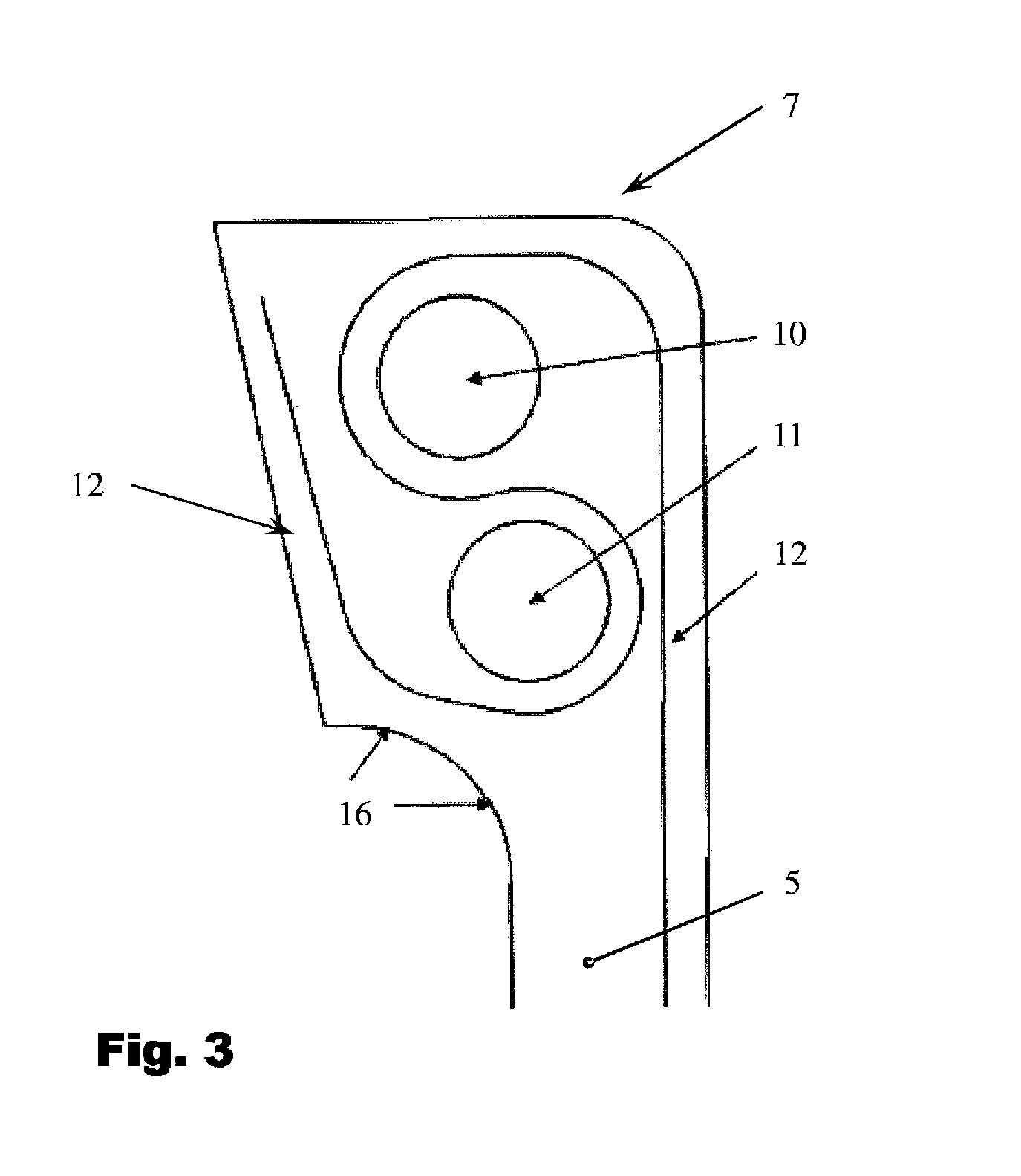
[0023]FIG. 3 shows, in an enlarged view, the lower bead ring 7 of the pneumatic spring bellows 5 with the bead ring being fastened to the unsprung bogie 2. The bead ring 7 is provided with a core made of two core rings 10 and 11 positioned separately in the bead ring. The reinforcement elements 12 are ...


PUM


Abstract

The invention is directed to a pneumatic spring device (3) of a rail vehicle (1). The device includes a pneumatic spring bellows (5), which is provided on both ends with a bead ring (6, 7), wherein the bead ring (6, 7) has a core made of two core rings (10, 11, 13, 14) positioned separately in the bead ring and the reinforcement elements (12) are guided in an S shape between the core rings and loop around the latter.

Description

CROSS REFERENCE TO RELATED APPLICATIONS[0001]This application is a continuation application of international patent application PCT / EP 2010 / 068705, filed Dec. 2, 2010, designating the United States and claiming priority from German application 10 2010 000 290.9, filed Feb. 3, 2010, and the entire content of both applications is incorporated herein by reference.FIELD OF THE INVENTION[0002]The invention relates to a pneumatic spring device for a rail vehicle, comprising a pneumatic spring bellows which is arranged between a sprung chassis (a rail vehicle) and an unsprung subframe (bogie) and is provided with reinforcement, which are embedded in the bellows material, as reinforcing elements, wherein individual layers or a plurality of layers of reinforcements or fabric layers made of reinforcements can be provided. At both ends, the pneumatic spring bellows has a bead ring for fastening or clamping the pneumatic spring bellows to correspondingly designed stop rings (flanges) of the cha...

Claims


Application Information

Patent Timeline
Patent Type & Authority Patents(United States)
IPC IPC(8): F16F9/05F16F9/04
CPCF16F9/0454F16F9/0409
Inventor GEDENK, VOLKERHESSE, BERND
Owner CONTITECH LUFTFEDERSYST
Learn More