Cooling fin stamping and riveting structure

A technology of heat dissipation fins and riveting structure, which is applied to heat exchange equipment, heat exchanger shells, lighting and heating equipment, etc., can solve the problems of unstable combination of heat dissipation fins, easy bending and heat dissipation efficiency, etc.

Pending Publication Date: 2019-10-29
HUANG TSUNG HSIEN YUAN SHAN HSIANG
View PDF2 Cites 2 Cited by
  • Summary
  • Abstract
  • Description
  • Claims
  • Application Information

AI Technical Summary

Problems solved by technology

[0005] In view of this, the present invention aims at the deficiencies in the prior art, and its main purpose is to provide a stamping and riveting structure of heat dissipation fins, which can effectively solve the problems of the existing heat dissipation fins that are not stable in combination, easy to bend, and have high heat dissipation efficiency. low problem

Method used


Image

  • Cooling fin stamping and riveting structure
  • Cooling fin stamping and riveting structure
  • Cooling fin stamping and riveting structure

Examples


Embodiment Construction

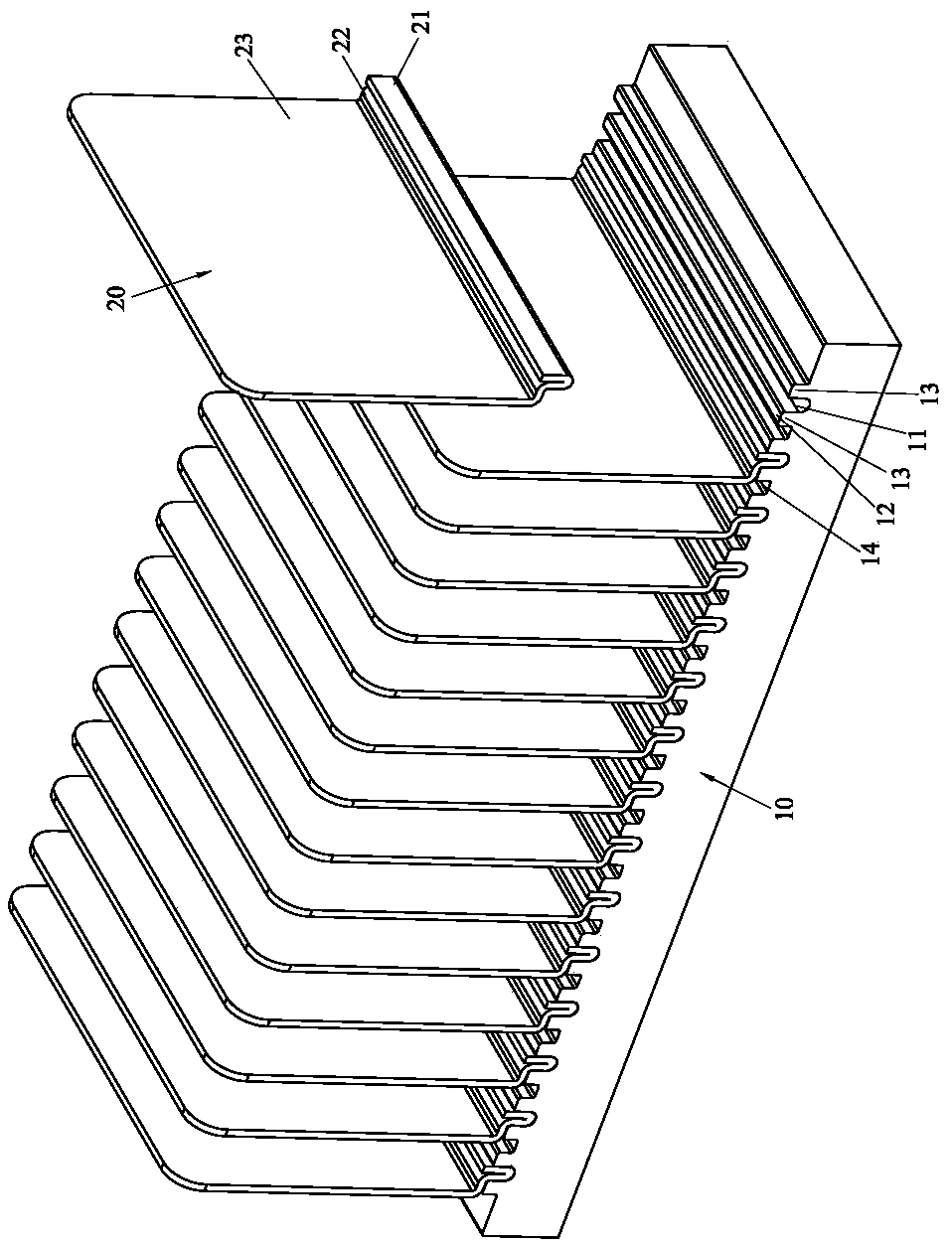
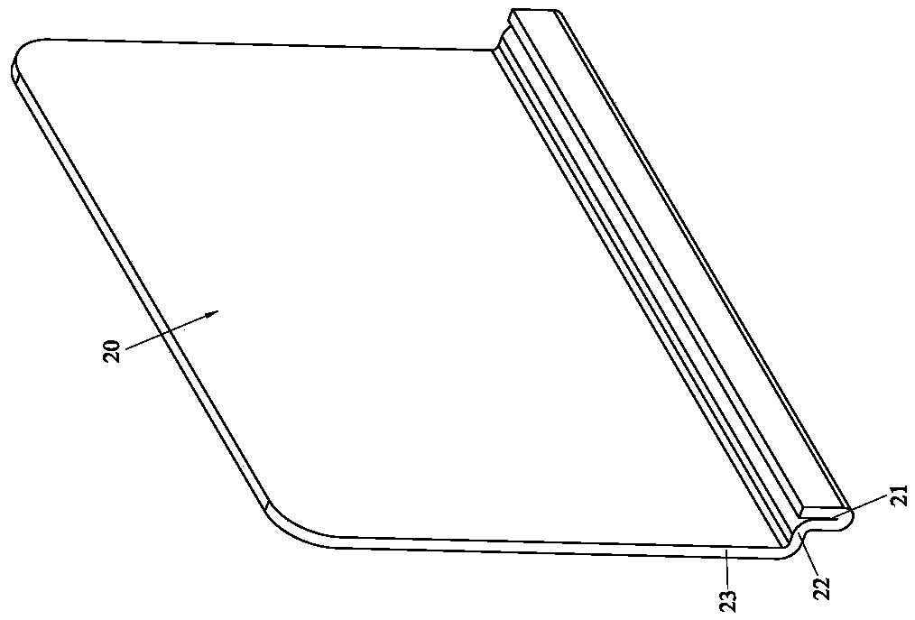
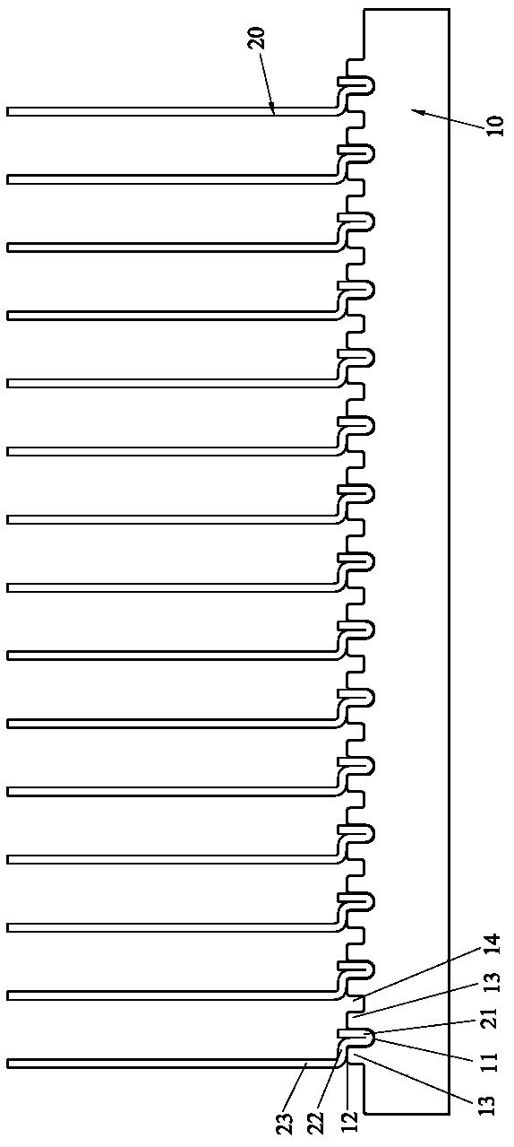
[0045] Please refer to Figure 1 to Figure 6 As shown, it shows the specific structure of the first preferred embodiment of the present invention, including the base 10 and the cooling fins 20 .

[0046] The surface of the base 10 is provided with a groove 11 for inserting the cooling fins 20. At least one side of the opening of the groove 11 has a contact surface 12; in this embodiment, the base 10 is a copper, aluminum, copper Base alloy or aluminum base alloy base, both sides of the groove 11 are formed with a strip-shaped boss 13, the contact surface 12 is located on the top surface of one of the strip-shaped bosses 13, and the contact surface 12 is The horizontal plane, but not limited to the horizontal plane, can also be an inclined plane; and, the grooves 11 are arranged in parallel at intervals, and between two adjacent grooves 11 are recessed grooves 14 formed on the surface of the base 10 , to increase the heat dissipation area and improve the ventilation and heat d...


PUM


Abstract

The invention discloses a cooling fin stamping and riveting structure. The structure comprises a base and cooling fins. Grooves are formed in the surface of the base. At least one sides of openings ofthe grooves are provided with contact surfaces correspondingly. Each cooling fin comprises an implanting portion, a connecting portion and a body portion which are connected together, wherein the implanting portion is of a reflexed structure and embedded into the corresponding groove, and the connecting portion extends to one side relative to the implanting portion and abuts against the corresponding contact surface. By forming the connecting portions on the cooling fins correspondingly and making the connecting portions make contact with the contact surfaces on the base, on the one hand, onesides of the cooling fins can be stably supported, the implanting portions of the reflexed structures are better stressed when being stamped by a stamping punch, the cooling fins are more reliably bonded to the base, the height of the cooling fins is further decreased, bending deformation is not prone to occurring, deflection is avoided, and it is ensured that cooling flow channels formed betweenthe cooling fins are straight; and on the other hand, heat on the base can be directly transmitted to the connecting portions, and the cooling efficiency is effectively improved.

Description

technical field [0001] The invention relates to the technology in the field of heat sinks, in particular to a stamping and riveting structure of heat dissipation fins. Background technique [0002] The combination of heat dissipation fins and base of conventional heat sinks, in addition to the traditional welding technology, also uses stamping methods, the heat dissipation fins are first inserted into the preset grooves or clamping protrusions of the base, and then stamped The punch is punched, so that the cooling fins are clamped and combined with the groove (or clamping protrusion) of the base, such as the US Patent No. 5014776 case, which is to make the side walls of the grooves on both sides produce stamping and pushing deformation , and then the heat dissipation fins can be clamped to achieve the purpose of combining the heat dissipation fins and the base. [0003] The above-mentioned prior patent technology only uses the extrusion deformation on both sides of the groo...

Claims


Application Information

Patent Timeline
Patent Type & Authority Applications(China)
IPC IPC(8): F28F9/26
CPCF28F9/262
Inventor 黄崇贤
Owner HUANG TSUNG HSIEN YUAN SHAN HSIANG
Why Eureka
Try Eureka