Eureka AIR delivers breakthrough ideas for toughest innovation challenges, trusted by R&D personnel around the world.

Steel ladle bottom argon blowing control system and method

A control system, bottom argon blowing technology, applied in the field of steelmaking, can solve problems such as uneven flow distribution of argon gas, increase of inclusions in molten steel, failure to remove inclusions, etc.

Pending Publication Date: 2019-10-29
沈阳人和机械制造有限公司
View PDF8 Cites 8 Cited by
  • Summary
  • Abstract
  • Description
  • Claims
  • Application Information

AI Technical Summary

Problems solved by technology

The existing technical solutions for the control of argon blowing at the bottom of the ladle have the following defects: (1) the phenomenon of uneven flow distribution of argon often occurs, and if the argon flow is too large, it will blow through the liquid surface of molten steel and cause splashing, resulting in exposed oxidation of molten steel, inclusions If the flow rate of argon is too small, it cannot be stirred quickly, and the purpose of removing inclusions cannot be achieved; (2) There is no operation terminal on site, resulting in high labor intensity for workers; (3) The degree of automation of the argon blowing control system at the bottom of the ladle is backward , does not take measures to collect process data for ladle bottom blowing argon control, and does not provide a traceable path for process data for ladle bottom blowing argon control

Method used


Image

  • Steel ladle bottom argon blowing control system and method
  • Steel ladle bottom argon blowing control system and method
  • Steel ladle bottom argon blowing control system and method

Examples


Embodiment Construction

[0034] In order to be able to understand the above objectives, features and advantages of the present invention more clearly, the present invention will be further described in detail below in conjunction with the accompanying drawings and specific embodiments. It should be noted that the embodiments of the application and the features in the embodiments can be combined with each other if there is no conflict.

[0035] In the following description, many specific details are explained in order to fully understand the present invention. However, the present invention can also be implemented in other ways different from those described here. Therefore, the scope of protection of the present invention is not limited to the specific details disclosed below. Limitations of the embodiment.

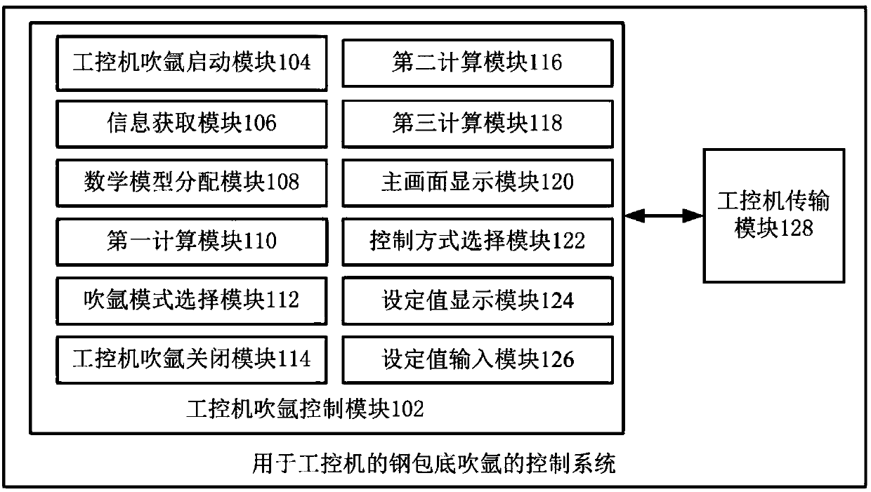
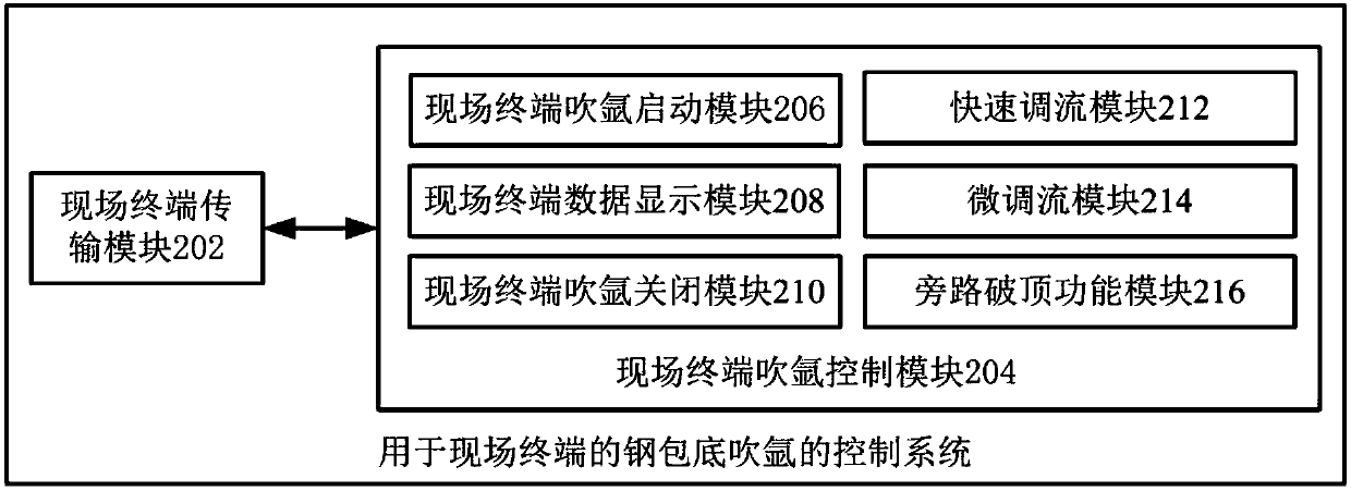
[0036] Such as figure 1 As shown, a control system for blowing argon at the bottom of a ladle of an industrial computer, the industrial computer and the field terminal both interact with a PLC control...


PUM


Abstract

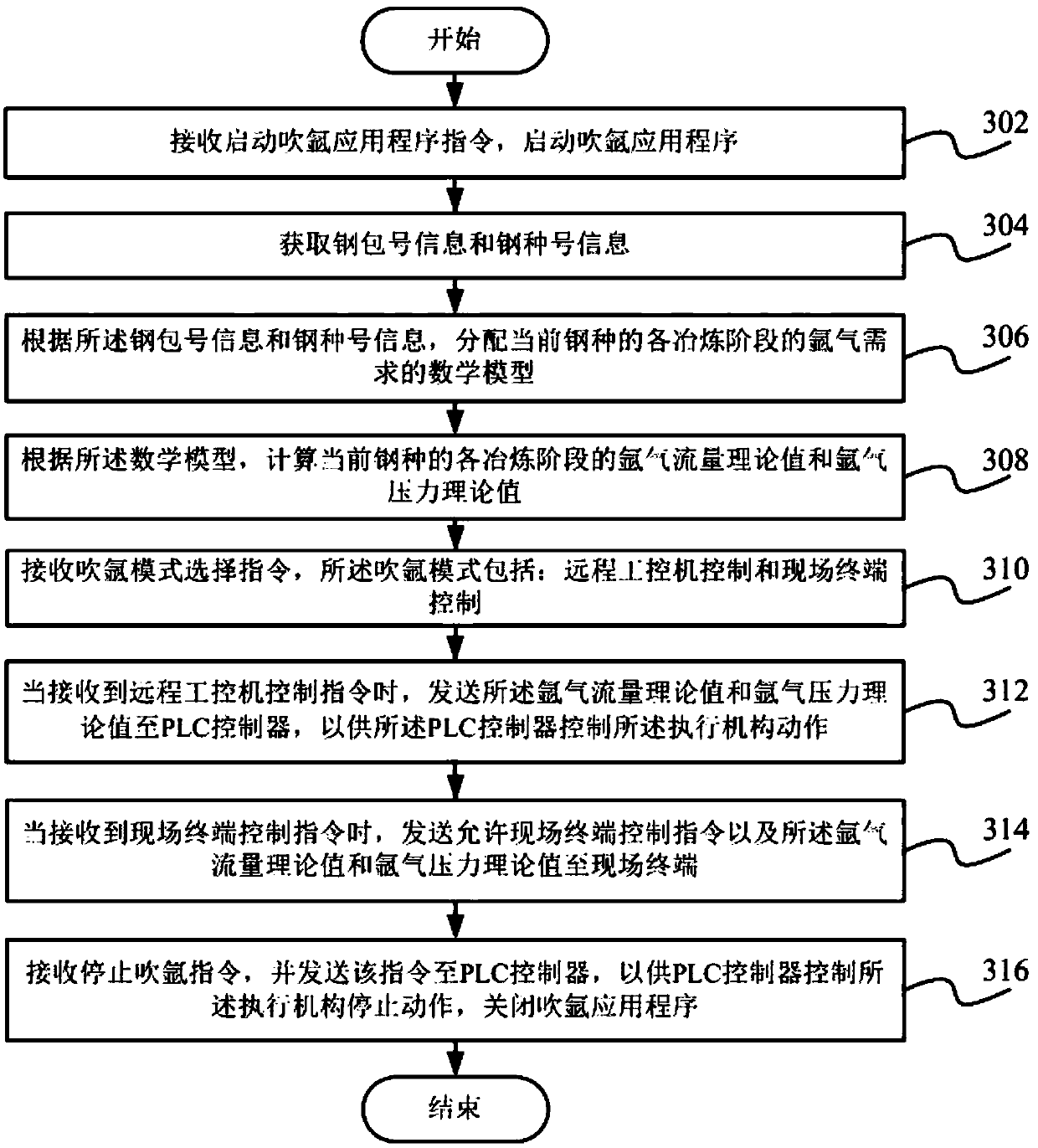
The invention discloses a ladle bottom argon blowing control system and a method. The ladle bottom argon blowing control system for an industrial personal computer comprises an industrial personal computer argon blowing control module and an industrial personal computer transmission module, wherein the industrial personal computer argon blowing control module interacts with the industrial personalcomputer transmission module, and the industrial personal computer argon blowing control module comprises an industrial personal computer argon blowing starting module, an information acquisition module, a mathematical model distribution module, an argon blowing mode selection module, a first calculation module and an industrial personal computer argon blowing closing module. The ladle bottom argon blowing system for the industrial personal computer establishes an argon blowing mathematical model for the all-steel type smelting outside a furnace, and different mathematical models can be automatically selected according to different steel types to realize the full-automatic adjustment of argon pressure and flow control in the steel ladle argon blowing process, and meanwhile, two control modes of a remote industrial personal computer control and an on-site terminal control are provided, so that different requirements of technical personnel on a steel ladle bottom argon blowing control are adapted.

Description

Technical field [0001] The invention relates to the technical field of steelmaking, in particular to a control system and method for blowing argon at the bottom of a ladle. Background technique [0002] The argon blowing control system at the bottom of the ladle currently in use usually uses two independent air-permeable bricks to control the argon blowing at the bottom of the ladle. The existing technical solutions for argon blowing control at the bottom of the ladle have the following defects: (1) Uneven distribution of argon flow often occurs. If the flow of argon is too high, it will blow through the molten steel surface and splash, causing the molten steel to be exposed to oxidation and inclusions. If the argon flow is too small, it will not be able to stir quickly, and the purpose of removing the inclusions will not be achieved; (2) There is no operation terminal on site, resulting in high labor intensity for workers on site; (3) The automation of the ladle bottom argon blo...

Claims


Application Information

Patent Timeline
IPC IPC(8): C21C7/072
CPCC21C7/072C21C7/0075Y02P10/25
Inventor 刘志飚张帆王照志赵晶刘庆文孙宏勇袁志刚张功让
Owner 沈阳人和机械制造有限公司
Why Eureka
Eureka Blog
Learn More