An automatic wind source system for rolling stock
What is Al technical title?
Al technical title is built by PatSnap Al team. It summarizes the technical point description of the patent document.
A wind source and vehicle technology, applied in motor vehicles, vehicle parts, railway vehicles, etc., can solve the problems that the locomotive cannot achieve automatic bow lift, the locomotive cannot be started, and the failure rate is high, and achieves compact structure, reduced failure rate, and stress. uniform effect
Active Publication Date: 2020-05-22
JIANGXI CHANGHE AUTO
View PDF1 Cites 0 Cited by
Summary
Abstract
Description
Claims
Application Information
AI Technical Summary
This helps you quickly interpret patents by identifying the three key elements:
Problems solved by technology
Method used
Benefits of technology
Problems solved by technology
[0002] The train air source system is the basis of the whole vehicle air pipeline system. It is a system that mainly provides high-quality, clean, dry and stable compressed air to the train brake and train auxiliary air equipment. It is used as the air storage cylinder of the locomotive. When the compressed air leaks completely due to various reasons or the pressure is insufficient, the locomotive cannot realize the operation functions of automatic bow raising and closing the main break, thus causing the locomotive to fail to start, and a device that can generate auxiliary compressed air through the power supply of the battery is essential
[0003] The existing automatic air source is controlled by four one-way valves, and the air source is transported to the quick connector through eight rubber hoses, resulting in high cost, long pipeline, and easy aging, resulting in frequent air leakage and high failure rate
Method used
Image
Click on the blue label to locate the original text in one second.
Reading with bidirectional positioning of images and text.
Examples
Embodiment Construction
[0022] The following will clearly and completely describe the technical solutions in the embodiments of the present invention with reference to the accompanying drawings in the embodiments of the present invention. Obviously, the described embodiments are only some, not all, embodiments of the present invention. Based on the embodiments of the present invention, all other embodiments obtained by persons of ordinary skill in the art without making creative efforts belong to the protection scope of the present invention.
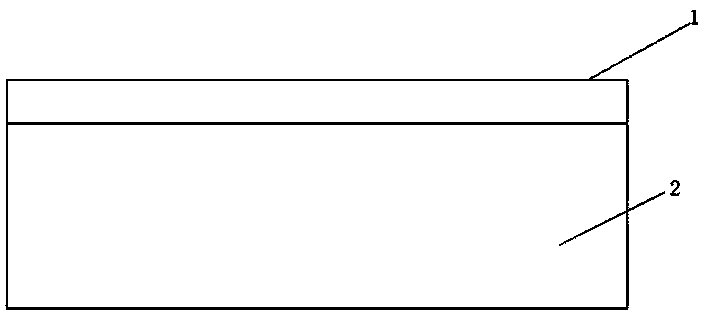
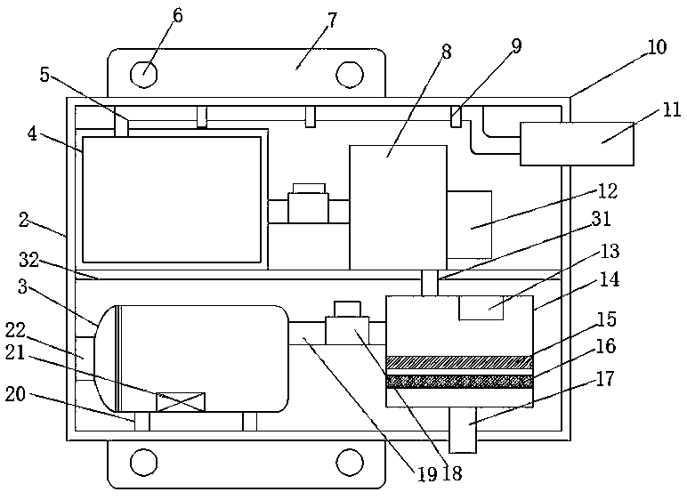
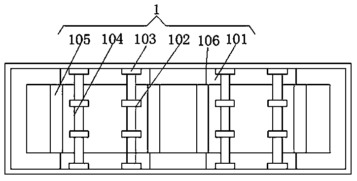
[0023] An embodiment of the present invention provides an automatic wind source system for rolling stock, such as Figure 1-4 As shown, including the main frame 1, the interior of the main frame 1 is provided with a fixed cross bar 105, and one side of the fixed cross bar 105 is provided with a movable cross bar 104. By setting the movable cross bar 104, a hook 102 is added on the wind source device 2 , so that the air source device 2 is on the movable cross b...
PUM
Abstract
The invention provides an automatic wind source system of a rolling stock, and relates to the field of automobile manufacturing. The system comprises a main frame. A wind source device is fixedly installed at the bottom of the main frame, an air suction valve air inlet pipe is arranged inside the wind source device, a stainless steel ribbon is arranged inside the air suction valve air inlet pipe,and the air suction valve air inlet pipe is fixedly installed at the inner wall of the top of the air source device through the stainless steel ribbon. According to the automatic wind source system ofthe rolling stock, due to an electromagnetic valve, the phenomenon that in the working process, an air compressor is suddenly powered off and stopped and then powered on again, so that the air compressor breaks down can be avoided, the fault rate is greatly lowered, the maintenance cost is lowered, due to an air guiding pipe, by adopting the high and low temperature resistance material, the pipeline is short, the manufacturing cost is low, the pipe is not prone to aging, the phenomena of air leakage and electric leakage caused by high and low temperature can be avoided, air leakage is not likely to be caused, due to the air compressor, an adsorption drier, a dust removal filter, an air storage cylinder and various pipelines, the structure is compact, stress at the bottom of the main frameis uniform, the service life of the whole system is prolonged, and the occupied space is small.
Description
technical field [0001] The invention relates to the technical field of automobile manufacturing, in particular to an automatic wind source system for rolling stock. Background technique [0002] The train air source system is the basis of the whole vehicle air pipeline system. It is a system that mainly provides high-quality, clean, dry and stable compressed air to the train brake and train auxiliary air equipment. It is used as the air storage cylinder of the locomotive. When the compressed air leaks completely due to various reasons or the pressure is insufficient, the locomotive cannot realize the operation functions of automatic bow raising and closing the main break, thus causing the locomotive to fail to start, and a device that can generate auxiliary compressed air through the power supply of the battery is essential . [0003] The existing automatic air source is controlled by four one-way valves, and the air source is transported to the quick connector through eigh...
Claims
Application Information
Patent Timeline
Application Date:The date an application was filed.
Publication Date:The date a patent or application was officially published.
First Publication Date:The earliest publication date of a patent with the same application number.
Issue Date:Publication date of the patent grant document.
PCT Entry Date:The Entry date of PCT National Phase.
Estimated Expiry Date:The statutory expiry date of a patent right according to the Patent Law, and it is the longest term of protection that the patent right can achieve without the termination of the patent right due to other reasons(Term extension factor has been taken into account ).
Invalid Date:Actual expiry date is based on effective date or publication date of legal transaction data of invalid patent.