
Plane winding machine

A winder and plane technology, which is applied in the direction of winding strips, thin material processing, transportation and packaging, etc., can solve the problems of film waste and unusability, and achieve the goal of reducing resource waste, improving pass rate, and cutting flat and beautiful Effect

Active Publication Date: 2019-10-25
浙江达尔美塑胶有限公司
View PDF8 Cites 3 Cited by
  • Summary
  • Abstract
  • Description
  • Claims
  • Application Information

AI Technical Summary

Problems solved by technology

[0004] The above-mentioned existing technical solutions have the following defects: the cutting knife is driven by the trolley to cut the film. Since the extension direction of the guide rail is straight, the film is in a moving state during the film winding process, that is, the cutting knife moves along the transverse direction. , the film moves in the vertical direction, and finally the cutting of the film is carried out along a curved path with a certain radian, so that the tail end of the film that has been wound and the head end of the film to be wound cannot be used, resulting in a a lot of waste

Method used

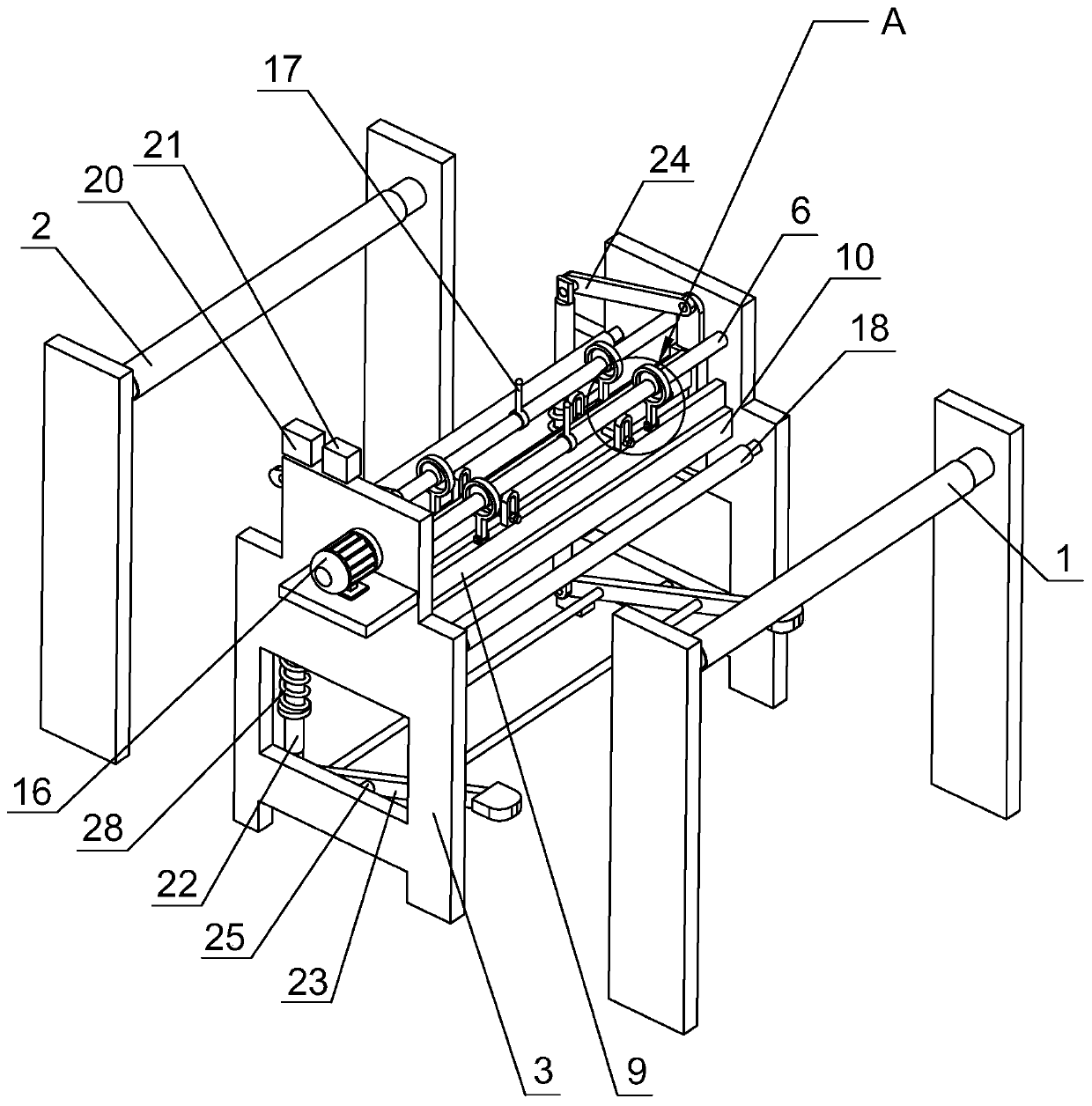
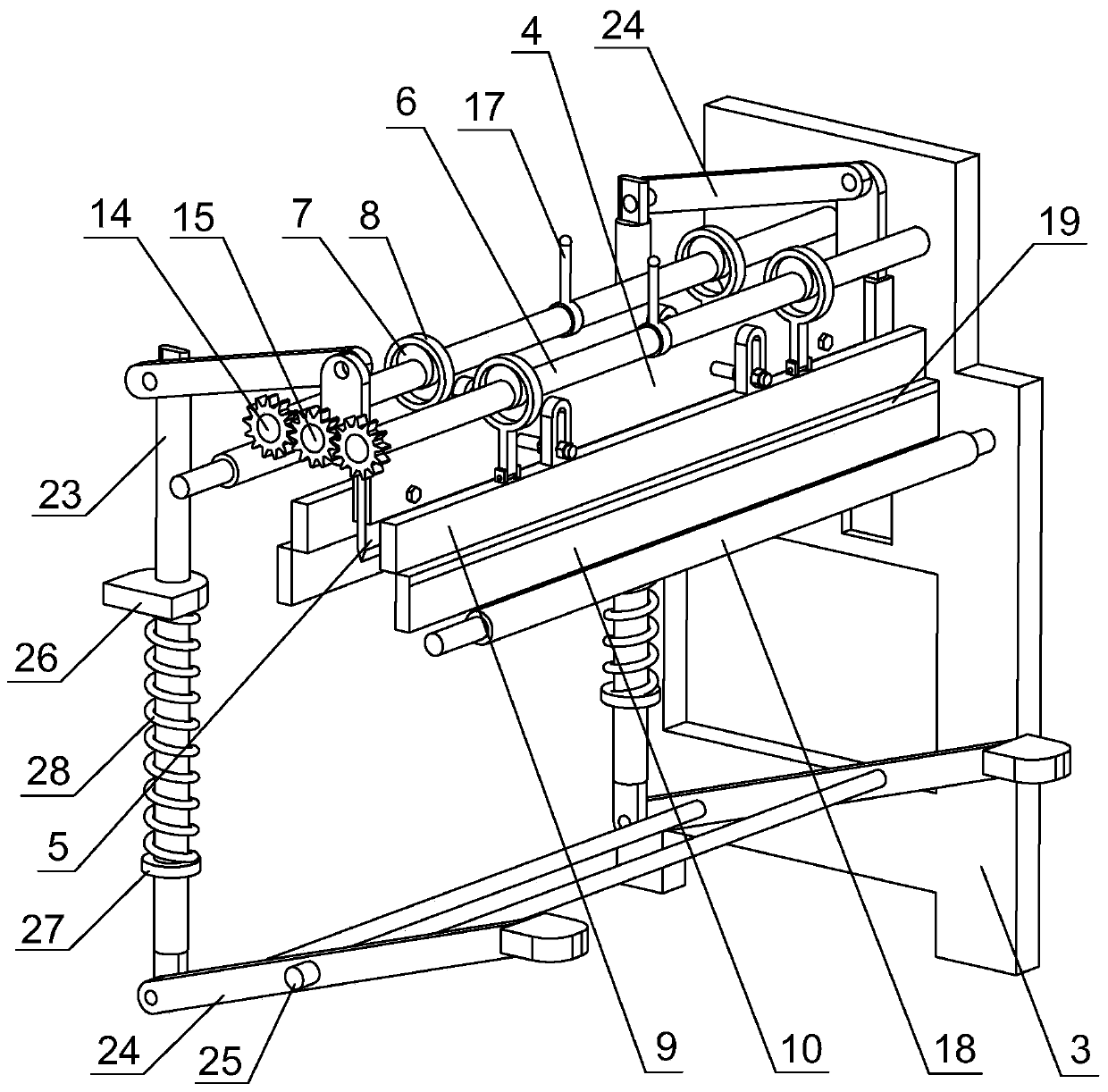
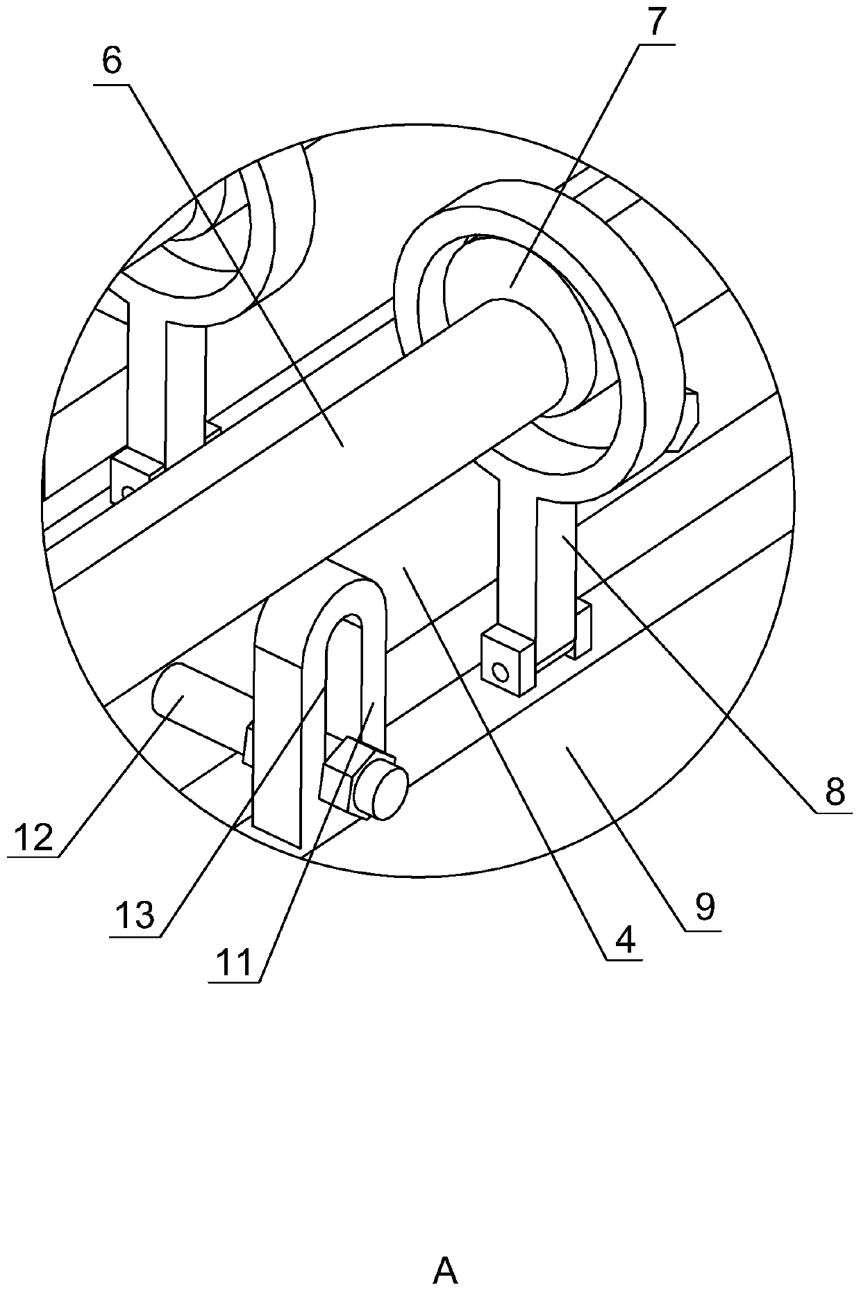

Image

  • Plane winding machine
  • Plane winding machine
  • Plane winding machine

Examples


Embodiment Construction

[0034] The present invention will be described in further detail below in conjunction with the accompanying drawings.

[0035] refer to figure 1 , is a plane winder disclosed by the present invention, comprising an unwinding roller 1 and a winding roller 2 for winding a film, the axis of the winding roller 2 is arranged parallel to the axis of the unwinding roller 1, and the unwinding roller Frame 3 is fixed between 1 and winding roller 2. refer to figure 2 , the inside of the frame 3 is provided with a knife rest 4 for lifting, one side of the knife rest 4 is fixedly embedded with a cutting knife 5, the cutting knife 5 extends along the length direction of the knife rest 4, and the blade of the cutting knife 5 faces away from the knife One side of rack 4 is set. The cutting knife 5 is used to cut the film. After the film winding on the winding roller 2 is completed, the lifting knife rest 4 drives the cutting knife 5 to descend, thereby cutting the film directly below the...


PUM


Abstract

The invention discloses a plane winding machine, and relates to the technical field of film winding equipment. The machine solves the problem that a large quantity of films are wasted because the films are not positioned and the cutting path is curved.. The plane winding machine comprises an unwinding roller and a winding roller for winding a film, wherein a rack is fixed between the unwinding roller and the winding roller; a cutter holder is arranged in the rack in a lifting manner; a cutter is fixedly arranged on one side of the cutter holder in an embedded manner; rotating rods are rotatably arranged on two sides of the cutter holder respectively; cams are connected to two ends of each rotating rod fixedly and coaxially; a press rod sleeves the peripheral side of each came, and two of the press rods are jointly hinged with an upper positioning plate; a lower positioning plate is fixed in the rack; a guiding assembly is arranged between the upper positioning plate and the cutter holder. According to the plane winding machine, the upper positioning plate and the lower positioning plate are combined, so that the film can be conveniently positioned and clamped; with the film is cutby the cutter, the cutting speed is high, so that the surface of the film is flatter and attractive, waste of film resources is reduced, and production efficiency is improved.

Description

technical field [0001] The invention relates to the technical field of film winding equipment, in particular to a plane winding machine. Background technique [0002] PVC film is a very popular and widely used synthetic material. During the production process, the complete PVC film produced is rewound at the end of the assembly line by using a reeling roller. After the rewinding is completed, the staff needs to take a knife Quickly swipe from one end of the film to the other end to cut the film. Since the equipment is still running continuously during the film cutting process, there are certain safety hazards in manual film cutting, and the manually cut film has poor aesthetics and low quality. [0003] The authorized notification number is the Chinese patent of CN203699525U, which proposes an automatic cutting plane winder, including a plane winder, a guide rail, a motor and a driven sprocket bracket are installed on the frame of the plane winder, and on the motor shaft Th...

Claims


Application Information

Patent Timeline
IPC IPC(8): B65H19/26B65H19/30B65H26/00
CPCB65H19/26B65H19/30B65H26/00B65H2701/1133B65H2701/1752
Inventor 倪建赟吴斌吴南
Owner 浙江达尔美塑胶有限公司
Learn More