
Tray grabbing mechanism of bread tray collecting machine and bread tray collecting machine

A technology for grabbing mechanisms and pallets, which is applied in the direction of conveyors, conveyor objects, transportation and packaging, etc. It can solve the problems of inaccurate position correspondence of suction cups, influence on pallet grabbing and recycling, inconvenience, etc., and improve the gripping performance of suction cups , Improving the grasping accuracy and improving the effect of grasping efficiency

Pending Publication Date: 2020-02-21
北京市粮食科学研究院有限公司 +1
View PDF0 Cites 2 Cited by
  • Summary
  • Abstract
  • Description
  • Claims
  • Application Information

AI Technical Summary

Problems solved by technology

However, in the existing mechanical device, because the mechanical grasping mechanism adopts the electromagnetic sucker to absorb the raised part on the back of the tray, it is easy to cause the position of the sucker to be inaccurate, the grasping is not firm or the problem of dropping the tray occurs.
Moreover, because the electromagnetic chuck is used to absorb the tray, when the electromagnetic chuck is powered off, there is a defect that the tray cannot be quickly separated from the suction cup due to hysteresis, which affects the grabbing and recycling of subsequent trays
[0004] This shows that above-mentioned existing bread closing machine mechanical grasping mechanism still has inconvenience and defect, and urgently needs to be further improved

Method used


Image

  • Tray grabbing mechanism of bread tray collecting machine and bread tray collecting machine
  • Tray grabbing mechanism of bread tray collecting machine and bread tray collecting machine
  • Tray grabbing mechanism of bread tray collecting machine and bread tray collecting machine

Examples


Embodiment Construction

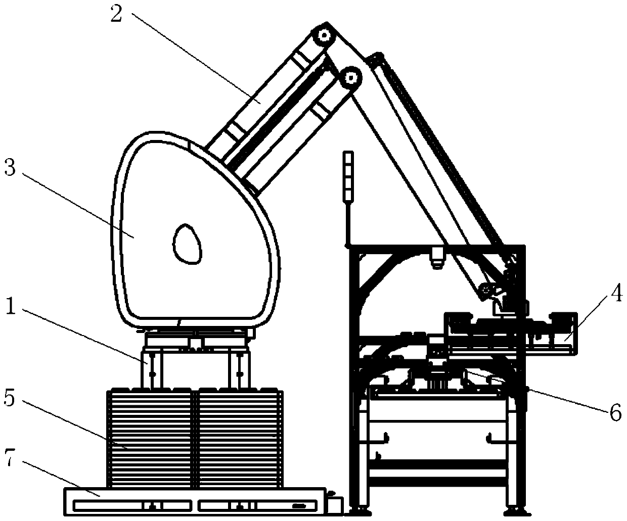
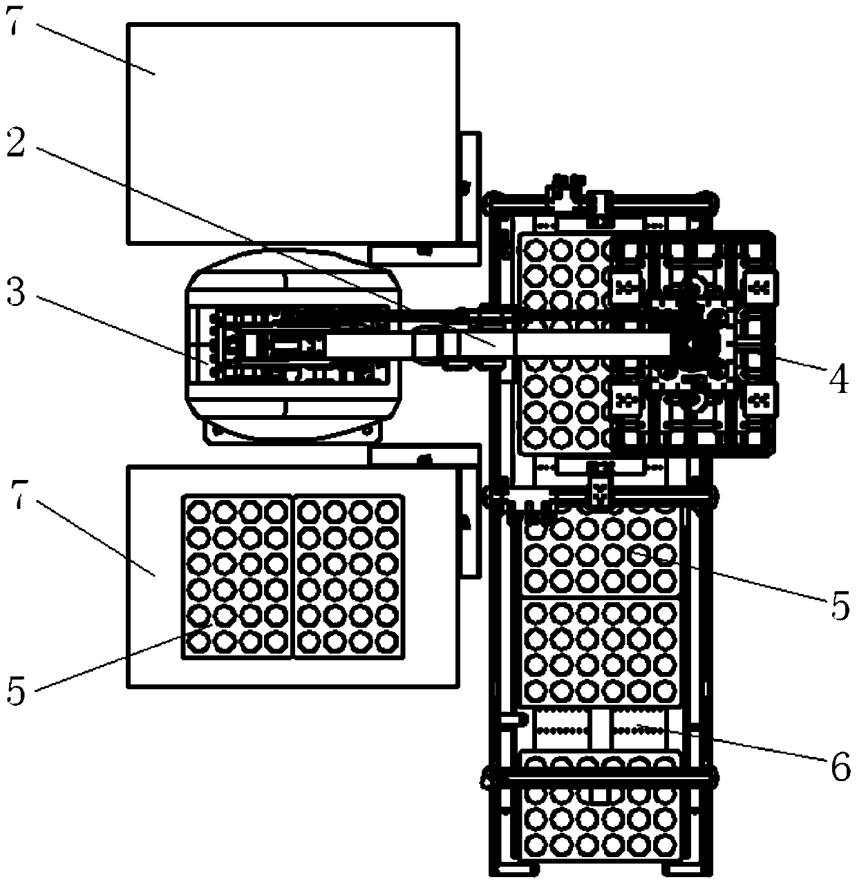
[0030] Refer to attached figure 1 and 2 As shown, the tray grabbing mechanism of the bread closing machine in this embodiment is used to automatically collect the trays conveyed on the tray conveyor belt. on status.

[0031] In order to realize fast and automatic tray collection, the tray grabbing mechanism of the bread closing machine in this embodiment is arranged next to the tray conveyor belt 6, which includes a base 1, a robot arm 2 and its control mechanism 3, and one end of the robot arm 2 is rotatable with the base 1 connected, and the other end is rotatably connected with the upper surface of the grabbing frame 4. The mechanical arm 2 of this embodiment adopts the existing four-link structure mechanical arm, and under the action of the control mechanism 3, it drives the grabbing frame 4 and the pallet 5 it grabs to move, and is used to grab the pallet 5 from the conveyor belt 6 to the On the stacking tray 7, the automatic stacking of pallets is realized.

[0032] ...


PUM


Abstract

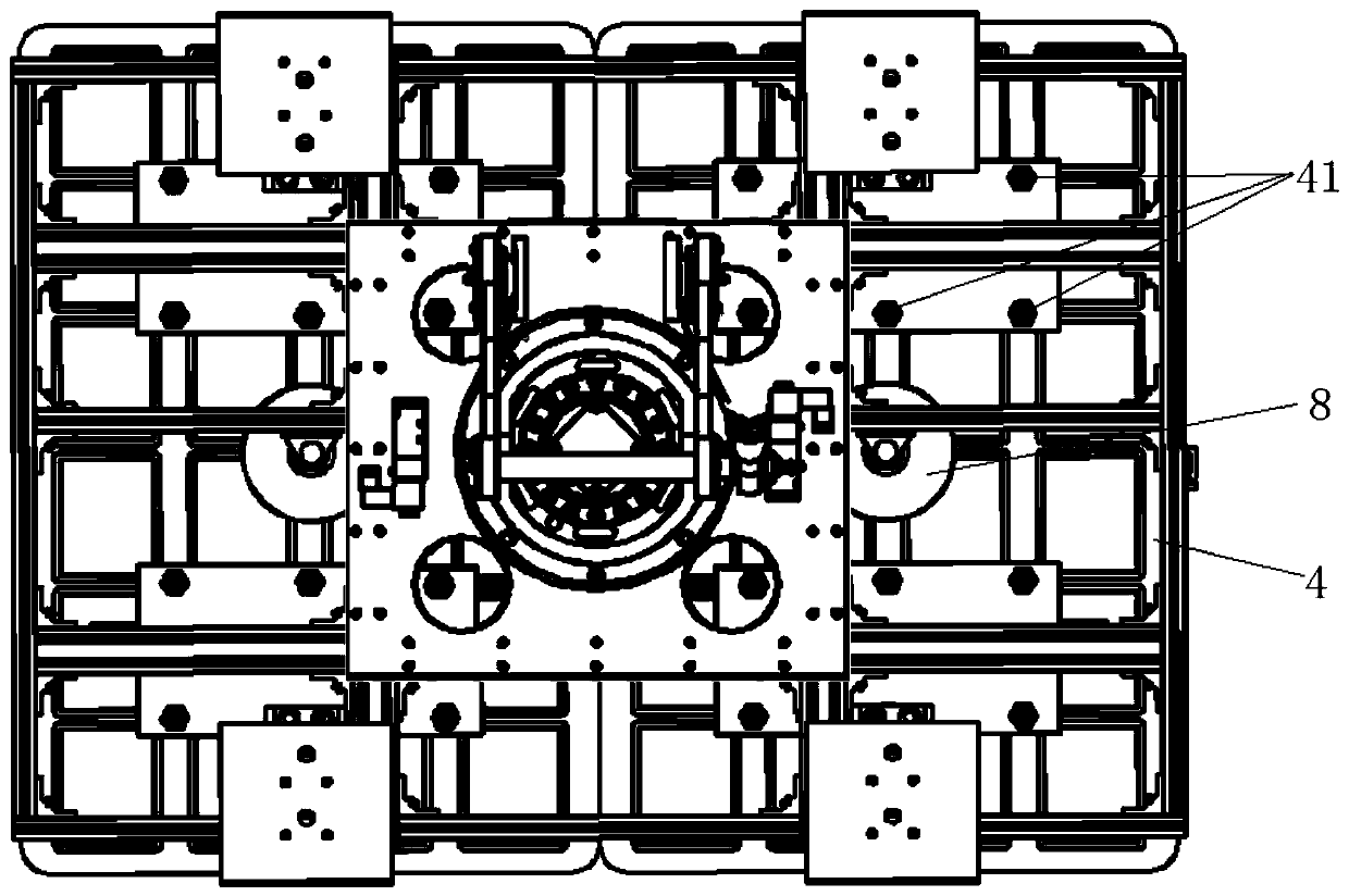
The invention discloses a tray grabbing mechanism of a bread tray collecting machine. The tray grabbing mechanism comprises a grabbing framework, a plurality of electromagnetic chucks are arranged onthe lower surface of the grabbing framework, and correspond to positions of protrusions on backs of trays, and separating air cylinders are furthermore arranged on the grabbing framework and used forachieving separation of the trays and the electromagnetic chucks when the electromagnetic chucks are powered off. At least one electromagnetic chuck set is arranged on the lower surface of the grabbing framework, and each electromagnetic chuck set corresponds to one tray, and comprises 12 chucks. The invention furthermore discloses the bread tray collecting machine. The bread tray collecting machine comprises the tray grabbing mechanism, a tray positioning and clamping device, a sensor detection mechanism and an abnormal tray monitoring mechanism. According to the tray grabbing mechanism, theelectromagnetic chucks correspond to the positions of the protrusions on the backs of the trays, and the tray grabbing precision is improved. Moreover, through the separating air cylinders, the problem that the trays cannot be quickly separated from the chucks due to the phenomenon of magnetic hysteresis is also effectively solved. The tray grabbing mechanism is precise in tray positioning, high in grabbing efficiency, capable of timely handling the occurrence of abnormal conditions, and high in automation degree.

Description

technical field [0001] The invention relates to the technical field of bread closing machines, in particular to a tray grabbing mechanism of the bread closing machine and the bread closing machine. Background technique [0002] In the industrial production process of bread, after the bread is baked and separated from the bread tray, the bread tray needs to be put away for use. The original collection method is manual collection of trays. Manual collection of trays is not only a heavy workload and high labor intensity, but also because of the high temperature of the trays, it is easy to cause scald accidents. [0003] In existing industrialized production, the device that adopts mechanical device to automatically collect the bread tray has also occurred. However, in the existing mechanical device, because the mechanical grasping mechanism adopts the electromagnetic sucker to absorb the raised part on the back of the tray, it is easy to cause the position of the sucker to be ...

Claims


Application Information

Patent Timeline
Patent Type & Authority Applications(China)
IPC IPC(8): B65G47/92B65G43/00
CPCB65G47/92B65G43/00B65G2201/0258
Inventor 兰向东白雪松邓峰陈钊付亭亭邱宇张海龙杨佳宁
Owner 北京市粮食科学研究院有限公司
Learn More