
Polyurethane composite material mixing machine for producing automobile roofs

A polyurethane composite material and car roof technology, which is applied in grain processing and other directions, can solve the problems of raw material loss, reduced cleanliness of the machine body, and the influence of raw material stirring and mixing, and achieve the effects of reducing raw material loss, fully stirring and mixing, and ensuring cleanliness

Pending Publication Date: 2019-10-25
南京汇科高分子材料有限公司
View PDF0 Cites 1 Cited by
  • Summary
  • Abstract
  • Description
  • Claims
  • Application Information

AI Technical Summary

Problems solved by technology

[0002] In the preparation process of polyurethane composite materials for automobile roofs, a mixer is often used. The mixer realizes the stirring and mixing of the raw materials. The particle size of the solid raw materials will directly affect the quality of the prepared products. During the storage process, there may be moisture, and the raw materials may be affected by the quality of the prepared products. When the raw materials of the mixer are introduced, the position of the feed port must be set, so that the imported raw materials will be stacked too concentratedly, which will affect the quality of the raw materials. The stirring and mixing of the machine body will inevitably cause raw material particles to adhere to the inner end wall after work. The adhesion of raw material particles will not only cause the loss of raw materials, but also reduce the cleanliness of the machine body, which will affect the follow-up products. The preparation causes interference. The existing mixer has low mixing efficiency and poor effect, and cannot achieve sufficient, uniform and efficient mixing. Therefore, a new solution is needed now

Method used


Image

  • Polyurethane composite material mixing machine for producing automobile roofs
  • Polyurethane composite material mixing machine for producing automobile roofs
  • Polyurethane composite material mixing machine for producing automobile roofs

Examples


Embodiment 1

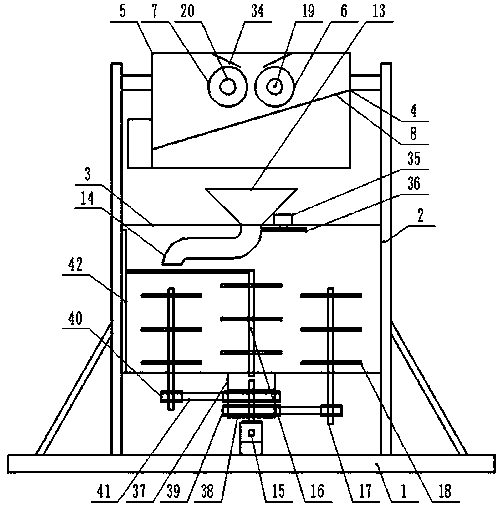
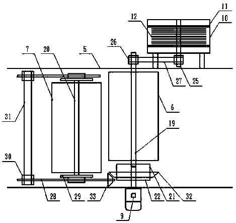
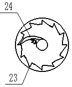
[0014] Example 1: see figure 1 , figure 2 , image 3 Now, a description will be given of a polyurethane composite mixing machine for producing automobile roofs provided by the present invention, which includes a foundation base 1 and a vertical fixing frame 2 evenly arranged on the upper middle side of the foundation base 1. The vertical fixing frame 2 A mixing box 3 is fixed between the lower ends, and a material preparation mechanism 4 is arranged between the upper ends of the vertical fixing frame 2. The material preparation mechanism 4 includes a material preparation box 5, and the upper end of the inner cavity of the material preparation box 5 is spaced parallel and horizontally. Some active grinding rollers 6 and driven grinding rollers 7, the inclined vibrating mesh screen 8 provided in the preparation box 5 and below the position of the active grinding roller 6, on the outer end wall of the preparation box 5 and corresponding to the position of the active grinding rolle...

Embodiment 2

[0015] Example 2: see figure 1 , figure 2 , image 3 Now, the present invention provides a description of a polyurethane composite material mixing machine for the production of automobile roofs. The lower end of the vertical fixing frame 2 and the upper end of the foundation base 1 are respectively provided with reinforcing ribs. A driving shaft 19 and a driven shaft 20 are arranged in parallel and horizontally at the upper end of the inner cavity of the preparation box 5, and the driving grinding roller 6 and the driven grinding roller 7 are respectively sleeved outside the driving shaft 19 and the driven shaft 20. The output shaft of the first motor 9 movably extends into the preparation box 5, the extension end of the output shaft of the first motor 9 is sheathed with a cylindrical transmission frame, and the inner port diameter of the cylindrical transmission frame is larger than that of the first The cross-sectional diameter of the output shaft of the motor 9, the cylindr...

Embodiment 3

[0016] Example 3: See figure 1 , figure 2 Now, the present invention provides a description of a polyurethane composite material mixing machine for producing automobile roofs. The first screw 25 and the driving shaft 19 are arranged parallel to each other at intervals, and the first screw 25 , The protruding ends of the active shaft 19 are respectively sleeved with a first pulley 26, a first belt 27 is sleeved between the outside of the first pulley 26, and the extrusion plate 11 is uniformly opened with through holes, respectively, The air filter housing 10 is provided with an air inlet and an air outlet on both end walls along the length direction of the first screw 25, respectively, the vertical fixing frame 2 is provided with a heating device, and the air inlet passes The pipe is in communication with the outlet end of the preparation box 5, the exhaust port is communicated with the inlet end of the heating device through the pipe, and the inlet end of the preparation box 5...


PUM


Abstract

The invention discloses a polyurethane composite material mixing machine for producing automobile roofs, and the machine comprises a base and a vertical fixing frame, a mixing box body is fixedly arranged between the lower end of the vertical fixing frame, a material preparing mechanism is arranged between the upper end of the vertical fixing frame, the material preparing mechanism comprises a material preparing box body, a driving grinding roller, a driven grinding roller, an inclined vibrating mesh screen, a first motor, a gas filtering shell, an extrusion plate and a filtering layer, the upper end of the mixing box body is provided with a round table-shaped material collecting bin, the inner top end of the mixing box body is movably connected with a curved material dispersing pipe corresponding to the position of a material inlet, a second motor is arranged at the middle side below the position of the mixing box body, a first stirring shaft is vertically arranged at the middle sideof the inner end of the mixing box body, the inner end edge of the mixing box body is uniformly and vertically provided with a second stirring shaft in equal radian, and the first stirring shaft and the second stirring shaft are respectively and uniformly provided with stirring rods at equal intervals.

Description

Technical field [0001] The invention relates to the processing field of polyurethane composite materials for automobile roofs, in particular to a mixing machine for producing polyurethane composite materials for automobile roofs. Background technique [0002] Polyurethane composite materials for automobile roofs often need to use a mixer during the preparation process. The mixer realizes the stirring and mixing of the raw materials. The particle size of the solid raw materials will directly affect the quality of the prepared products. Moisture may occur during the storage process. Moisture of the raw materials may affect the quality of the prepared products. When the raw materials of the mixer are introduced, the position of the feed inlet is set, so that the imported raw materials are too concentrated and piled up, which will affect the raw materials. The mixing and mixing of the machine body will inevitably adhere to the raw material particles on the inner end wall after workin...

Claims


Application Information

Patent Timeline
IPC IPC(8): B29B7/18B29B7/24B29B7/22B02C4/02B02C4/32B29B7/82B29B13/06B29B13/10
CPCB29B7/18B29B7/24B29B7/22B02C4/02B02C4/32B29B7/826B29B13/065B29B13/10
Inventor 魏永祥李军
Owner 南京汇科高分子材料有限公司
Learn More