
Finish machining system and finish machining method for reducing anisotropy of metal material

A technology of anisotropy and metal materials, applied in metal processing equipment, metal rolling, metal rolling, etc., can solve the problems that the anisotropy of materials cannot be improved, the rolling direction does not change, and the rolling stock cannot be rolled, etc. Achieve the effects of improving plasticity, reducing the tendency of side cracks, and improving quality

Pending Publication Date: 2019-10-25
UNIV OF SCI & TECH LIAONING
View PDF0 Cites 0 Cited by
  • Summary
  • Abstract
  • Description
  • Claims
  • Application Information

AI Technical Summary

Problems solved by technology

Longitudinal rolling can use the method of forced widening to obtain a larger width of the rolled piece, but the rolling direction does not change, so the anisotropy of the material cannot be improved
In order to improve the anisotropy of the material, the method of vertical and horizontal alternate reversible rolling is generally used, but this rolling method is limited by the width of the roll, and it cannot roll a long rolling piece.

Method used


Image

  • Finish machining system and finish machining method for reducing anisotropy of metal material
  • Finish machining system and finish machining method for reducing anisotropy of metal material
  • Finish machining system and finish machining method for reducing anisotropy of metal material

Examples


Embodiment 1

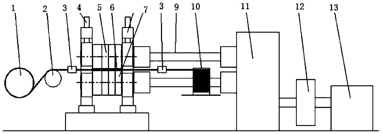
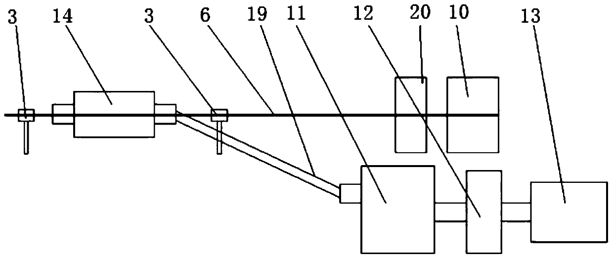
[0064] Such as figure 1 , figure 2 , Figure 9 with Figure 10 As shown, in this embodiment, a finishing system for reducing the anisotropy of metal materials consists of a two-roll rolling mill 14 (including an upper work roll 5, a lower work roll 8, a rolling mill archway 7, and a pressing device 4), a longitudinal The position control device 3, the rolling piece lateral feed control device 1, the speed divider 11 and the driving device 13 are used for rolling narrow rolling pieces.

[0065] In this embodiment, four plane segments 15 are correspondingly provided on the roll surfaces of the upper work roll 5 and the lower work roll 8 , and the rest are cylindrical roll surfaces 16 . The plane section 15 and the cylindrical roll surface 16 on the upper work roll 5 and the lower work roll 8 cooperate to form regular and spaced large roll gap areas and small roll gap areas along the circumferential direction of the roll surfaces.

[0066] In this embodiment, the rotating sp...

Embodiment 2

[0072] Such as Figure 4-Figure 6 , Figure 9 with Figure 10 As shown, in this embodiment, a finishing system for reducing the anisotropy of metal materials consists of a two-roll mill 14 (including an upper work roll 5, a lower work roll 8, a mill archway 7 and a pressing device 4), a longitudinal It consists of a position control device 3 , a rolling piece lateral feed control device 1 , a speed divider 11 and a driving device 13 . It is suitable for rolling the rolled pieces with large thickness and width and not easy to bend.

[0073] In this embodiment, the rotating speed of the upper work roll 5 and the lower work roll 8 is 60 rpm, the roll diameter is 300 mm, and the width of the roll surface is 100 mm. The width of the roll surface is divided into two parts, and each part is 50 mm wide. Two plane sections 15 are arranged on the roller surface along the circumferential direction, and the rest are cylindrical roller surfaces 16 . The circumferential length of each p...

Embodiment 3

[0080] Such as Figure 7-Figure 10 As shown, in this embodiment, a finishing system for reducing the anisotropy of metal materials consists of a two-roll rolling mill 14 (including an upper work roll 5, a lower work roll 8, a rolling mill archway 7 and a pressing device 4), a longitudinal It consists of a position control device 3 , a rolling piece lateral feed control device 1 , a speed divider 11 and a driving device 13 .

[0081] In this embodiment, the rotating speed of the upper and lower work rolls 5 and 8 is 30 rpm, the roll diameter is 300 mm, and the roll surface width is 100 mm. The roll surface is divided into two parts along the width direction, and each part is 50 mm wide. The roll surface is divided into 4 sections of planar sections 15 and 4 sections of cylindrical roll surfaces 16 along the circumference, wherein the circumferential length of each section of planar section 15 is 108 mm, and the circumferential length of each section of cylindrical roll surface ...


PUM


Abstract

The invention relates to a finish machining system and a finish machining method for reducing the anisotropy of a metal material. The system comprises two-roll mills, a speed splitting machine, a driving device, a discharging device, rolled piece longitudinal position control devices and a rolled piece transverse feed control device, wherein a rolling-mill housing on one side of each two-roll millis provided with a rolled piece inlet; a rolling-mill housing on the other side of each two-roll mill is provided with a rolled piece outlet; the rolled piece longitudinal position control devices are respectively arranged on the outer sides of the rolling-mill housings; the rolled piece transverse feed control device is arranged on the outer side of the rolled piece longitudinal position controldevice corresponding to one side of the rolled piece outlet; the discharging device is arranged on the outer side of the rolled piece longitudinal position control device corresponding to one side ofthe rolled piece inlet; and the roll surface of an upper working roll and / or a lower working roll is provided with a rolled piece nipping structure. By use of the finish machining system and the finish machining method disclosed by the invention, rolled pieces can greatly deform in the width direction or can periodically deform in the length direction as required, so that the anisotropy of the metal material is reduced, and mechanical properties of the metal material in all direction are uniform.

Description

technical field [0001] The invention relates to the technical field of rolling processing of metal materials, in particular to a finishing system and method for reducing the anisotropy of metal materials by adopting a transverse feed longitudinal rolling method relative to a rolling mill. Background technique [0002] Metal material rolling methods can generally be divided into longitudinal rolling, cross rolling, cross rolling and so on. The direction of metal flow during longitudinal rolling is the same as that of the roll surface. For example, the normal rolling of strips, round bars, bars, and section steels belongs to longitudinal rolling, and longitudinal rolling is also the main form of metal rolling. During cross rolling, the flow direction of the metal is perpendicular to the moving direction of the deformed metal, such as cross wedge rolling, etc., and some shaft products with variable cross-sections can be rolled. Cross rolling is between longitudinal rolling and...

Claims


Application Information

Patent Timeline
Patent Type & Authority Applications(China)
IPC IPC(8): B21B1/02B21B39/16B21B39/02
CPCB21B1/02B21B39/16B21B39/02
Inventor 胡小东赵红阳王振敏张举
Owner UNIV OF SCI & TECH LIAONING
Learn More