Eureka AIR delivers breakthrough ideas for toughest innovation challenges, trusted by R&D personnel around the world.

Anti-blocking chemical grinding equipment

An anti-clogging, chemical technology, applied in chemical instruments and methods, solid separation, filtration and screening, etc., can solve problems such as inability to screen, blockage of screening device screen holes, single grinding function, etc., to avoid blockage of screen holes and ensure continuous Sexuality, the effect of improving work efficiency

Active Publication Date: 2019-10-25
浙江浦江永进工贸有限公司
View PDF4 Cites 12 Cited by
  • Summary
  • Abstract
  • Description
  • Claims
  • Application Information

AI Technical Summary

Problems solved by technology

[0003] Traditional chemical grinding equipment has a simple structure and can only achieve a single grinding function. Generally, a closed grinding shell is used, which cannot be screened and requires multiple transfers of chemical raw materials. At the same time, traditional screening devices are prone to sieve blockage

Method used


Image

  • Anti-blocking chemical grinding equipment
  • Anti-blocking chemical grinding equipment
  • Anti-blocking chemical grinding equipment

Examples


Embodiment 1

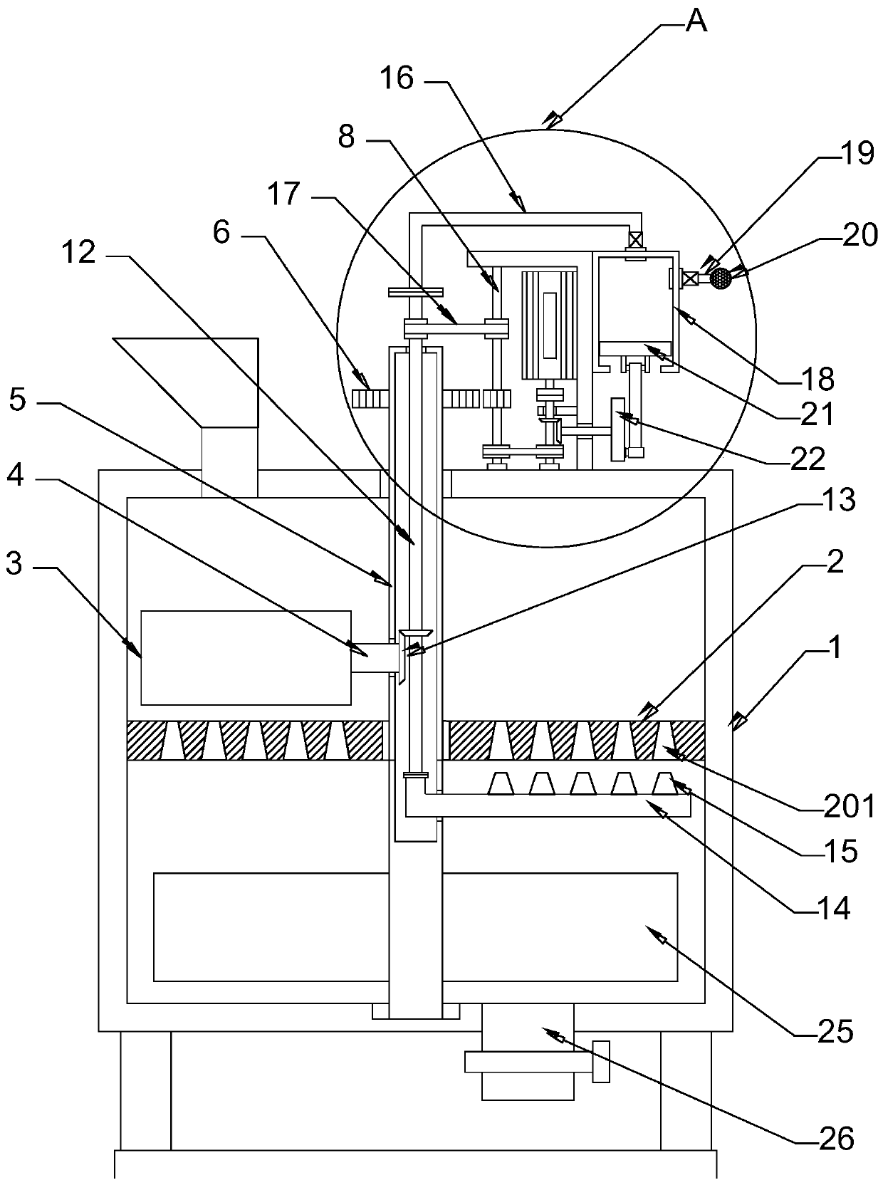
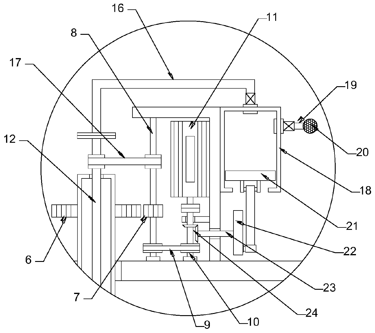
[0021] see Figure 1-4 , in the embodiment of the present invention, a kind of anti-clogging chemical grinding equipment comprises a grinding box 1 and a stirring plate 25; the grinding box 1 is provided with a grinding disc 2, and the grinding disc 2 is fixedly connected with the inner wall of the grinding box 1, and the grinding disc 2 is provided with evenly distributed sieve holes 201; the grinding roller 3 is arranged above the grinding disc 2, and the grinding roller 3 cooperates with the grinding disc 2 to grind and crush the chemical raw materials; the inner side of the grinding roller 3 is fixedly connected with a rotating shaft 4, and the rotating shaft 4 runs through a central cylinder 5 and is rotatably connected with the central cylinder 5; the central cylinder 5 penetrates through the grinding disc 2 and is rotatably connected with the grinding disc 2, the central cylinder 5 extends above the grinding box 1 and is sleeved and fixed with the first gear 6, The firs...

Embodiment 2

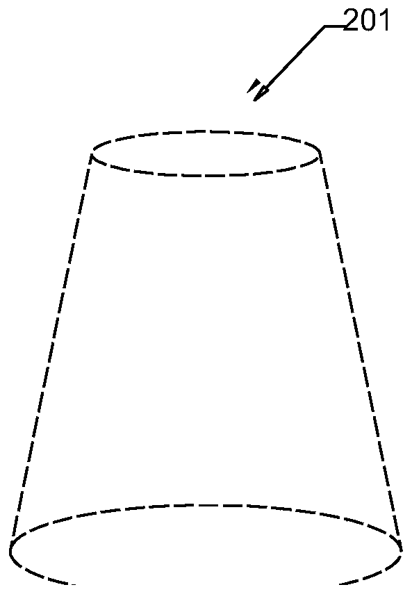
[0025] The difference between this embodiment and Embodiment 1 is that: the sieve hole 201 is in the shape of a circular platform, and the upper end opening of the sieve hole 201 is smaller than the lower end opening; The straight line where the diameter is located is parallel; the air injection pipe 14 is provided with evenly distributed air injection nozzles 15, and the air injection nozzle 15 is arranged opposite to the screen hole 201 on the grinding disc 2; the air injection pipe 14 runs through the central cylinder 5 and is fixed with the central cylinder Connection, the end of the jet pipe 14 is connected with a nested pipe 12 through a rotary joint, and the upper end of the nested pipe 12 is connected with an air intake pipe 16 through a rotary joint, and the air intake pipe 16 is connected with an air filling mechanism, which includes a piston cylinder 18 and a piston cylinder 18 It is connected with the intake pipe 16, the piston cylinder 18 is connected with the air ...


PUM


Abstract

The invention discloses anti-blocking chemical grinding equipment. The anti-blocking chemical grinding equipment comprises a grinding box, wherein a grinding disc in which sieve pores are uniformly distributed is arranged in the grinding box, a grinding roller is arranged above the grinding disc, an air injection pipe is arranged below the grinding disc, and air injection heads are uniformly distributed on the air injection pipe. According to the anti-blocking chemical grinding equipment, the grinding disc with the sieve pores and the grinding roller which can do a circular motion and can rotate are arranged, so that chemical materials are circularly rolled, and additionally, the materials are prevented from adhering to the grinding roller; the sieve pores in a shape of a circular truncated cone, the air injection pipe and a piston cylinder are formed and arranged, so that the sieve pores are injected and blown, the sieve pores are prevented from being blocked, the grinding continuityis guaranteed, and the working efficiency is improved.

Description

technical field [0001] The invention relates to the field of chemical equipment, in particular to anti-clogging chemical grinding equipment. Background technique [0002] All chemical machinery, including chemical equipment, are the tools used in chemical factories to realize chemical production. The normal operation of the production process of chemical products, the control and guarantee of product quality and output are inseparable from the adaptation and normalization of various chemical equipment. Operation, the selection and matching of chemical equipment must go through the detailed calculation, design, processing, manufacturing and matching of the entire chemical production process to meet the needs of chemical production. [0003] Traditional chemical grinding equipment has a simple structure and can only achieve a single grinding function. Generally, a closed grinding shell is used, which cannot be screened and requires multiple transfers of chemical raw materials....

Claims


Application Information

Patent Timeline
Patent Type & Authority Applications(China)
IPC IPC(8): B02C15/14B02C23/16B02C23/24B07B1/55
CPCB02C15/14B02C23/16B02C23/24B02C2015/002B02C2015/008B02C2023/165B07B1/55
Inventor 戴韵
Owner 浙江浦江永进工贸有限公司
Why Eureka
Eureka Blog
Learn More