A kind of crimping device and method for pcb board connector

A crimping device and PCB board technology, applied in the direction of assembling printed circuits, printed circuits, electrical components, etc. with electrical components, can solve the problems of difficult installation and use, shrinking needles, and different lengths of fisheye connector plugs, to ensure Electrical and mechanical properties, high reliability

Active Publication Date: 2021-11-16
TIANJIN JINHANG COMP TECH RES INST
View PDF7 Cites 0 Cited by
  • Summary
  • Abstract
  • Description
  • Claims
  • Application Information

AI Technical Summary

Problems solved by technology

[0004] New fisheye pin connectors (such as figure 1 shown) cannot be crimped with conventional crimping devices such as Figure 5 Shown) Press out 100% of the pins, pin shrinkage will appear, and the fisheye connector plugs have different lengths depending on the connector model (such as figure 2 and image 3 Shown are two kinds of fisheye connector plugs), a PCB board will consist of two different lengths of fisheye connector plugs
And the new fish-eye connector is an independent innovative domestic pin, which has not been widely used at present, so its installation and use have become difficult. The characteristic of this type of connector is that the fish-eye pin is wider than the cylindrical pin. It is necessary to set the crimping stroke and limit the connector to ensure that the pins will not be mispressed by the crimping device during crimping, and it is necessary to increase more contact area between the crimping device and the PCB board to ensure the Pins are pressed out
When the installation direction of the pins of the fisheye connector is inconsistent (such as image 3 As shown), two groups of pins in different positions are at 90 degrees to each other, and the front row has no supporting point, so it is easy to cause pin shrinkage during crimping

Method used


Image

  • A kind of crimping device and method for pcb board connector
  • A kind of crimping device and method for pcb board connector
  • A kind of crimping device and method for pcb board connector

Examples


Embodiment Construction

[0030] In order to make the purpose, content, and advantages of the present invention clearer, the specific implementation manners of the present invention will be further described in detail below in conjunction with the accompanying drawings and embodiments.

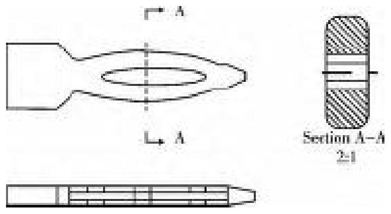
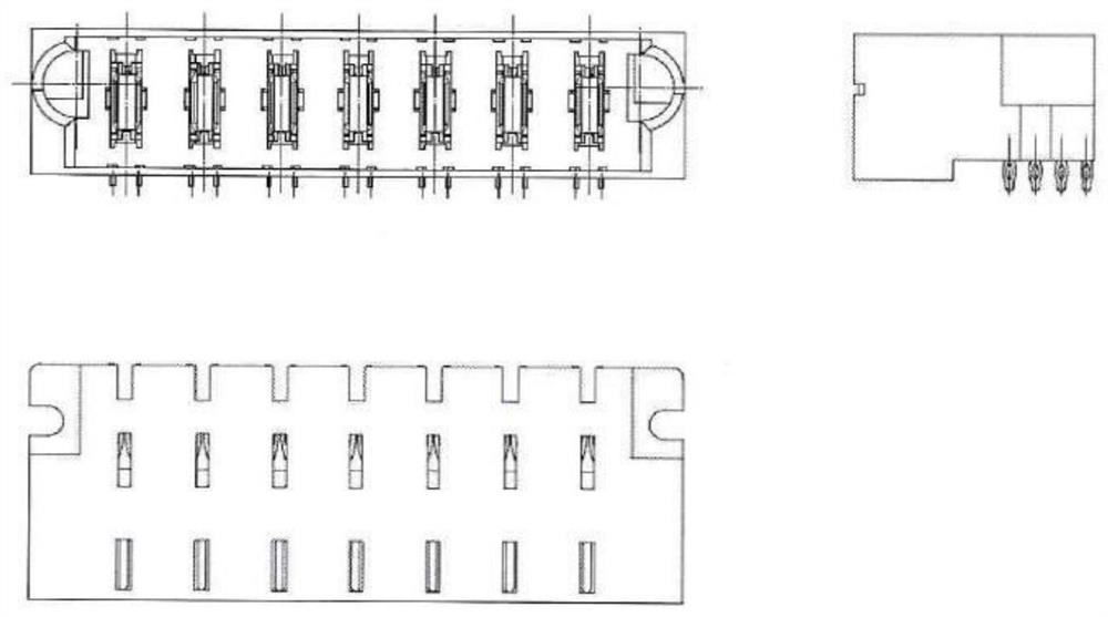
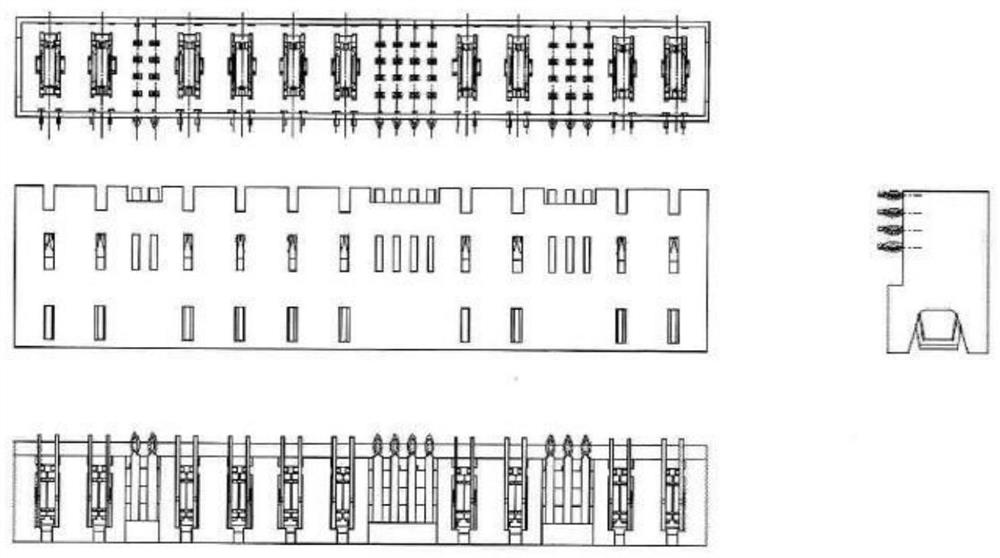
[0031] The present invention provides a crimping device for crimping a PCB board equipped with a fisheye connector, which consists of a first crimping module A and a second crimping module B, wherein as Figure 7 As shown, the first crimping module A is a crimping device for crimping the DP2ATJE0700-000 connector plug. The direction of the connector pins is uniform, and the direction of the first crimping module A is based on the printed board opening size of the PCB board. Designed as a horizontal slotted crimping device of the corresponding size, the slot depth is designed according to the length of the pin, which is 2 to 2.1 times the length of the pin, and the slot width is 1.65 to 2.54 of the distance between the t...


PUM


Abstract

The invention relates to a crimping device and method for a PCB board connector, and relates to the technical field of mechanical processing. The invention solves the crimping problem of a new type of fish-eye connector pin. During crimping, a crimping machine is used to carry out segmental crimping with a specified stroke. The length and width of the plastic shell are limited in two directions, and the crimping is more accurate after the two degrees of freedom are limited, which can ensure that the crimping device will not press the pin. The structure and size design of the crimping device can ensure 100% needle exit rate after crimping, no needle shrinkage phenomenon, high reliability after inspection and power-on test, and ensure the required electrical and mechanical properties.

Description

technical field [0001] The invention relates to the technical field of mechanical processing, in particular to a crimping device and method for a PCB board connector. Background technique [0002] Electrical connectors are mounted on PCB boards (PCB boards such as Figure 4 As shown), the components on the circuit are an indispensable part of electronic equipment. They not only serve as a communication bridge between the original isolated circuits in the circuit, so that the current can flow, but also play a stable connection and provide The role of high reliable plug-in times. [0003] The commonly used shape of the traditional connector terminal part is a cylindrical pin with the same pin direction, and the length of each connector is equal. The connector crimping method is to use a traditional crimping device (such as Figure 5 Shown) crimp each connector unit sequentially to form a set of connector plugs. [0004] New fisheye pin connectors (such as figure 1 shown) c...

Claims


Application Information

Patent Timeline
Patent Type & Authority Patents(China)
IPC IPC(8): H05K3/30
CPCH05K3/30H05K2201/10189
Inventor 王婷婷李铮曾立云曹建会刘欢刘志虎
Owner TIANJIN JINHANG COMP TECH RES INST
Why Eureka
Try Eureka