Beam column joint for connecting assembling type steel structure inner inserting plate square steel pipe column clamping plate

A technology for beam-column joints and insert plates, which is applied in building structures, buildings, etc., can solve the problems of difficulty in guaranteeing the quality of welds, affecting the mechanical properties of joints, slow construction speed, etc. Assembly speed effect

Inactive Publication Date: 2019-10-22
BEIJING UNIV OF TECH
View PDF7 Cites 1 Cited by
  • Summary
  • Abstract
  • Description
  • Claims
  • Application Information

AI Technical Summary

Problems solved by technology

[0005] In the traditional beam-column bolted-welded hybrid connection, the upper and lower flanges of the beam body adopt penetration groove welds. There are two connection methods for the beam body web, one is to use angle steel with high-strength bolts, and the other is to use high-strength bolts. The strength bolts are connected to the shear plate on the column flange. The construction speed of this connection is slow, and the quality of the weld is difficult to guarantee, which in turn affects the mechanical properties of the joint.

Method used


Image

  • Beam column joint for connecting assembling type steel structure inner inserting plate square steel pipe column clamping plate
  • Beam column joint for connecting assembling type steel structure inner inserting plate square steel pipe column clamping plate
  • Beam column joint for connecting assembling type steel structure inner inserting plate square steel pipe column clamping plate

Examples


Embodiment Construction

[0026] In order to make the purpose, technical solutions and advantages of the embodiments of the present invention clearer, the technical solutions in the embodiments of the present invention will be clearly and completely described below in conjunction with the drawings in the embodiments of the present invention. Obviously, the described embodiments It is a part of embodiments of the present invention, but not all embodiments. Based on the embodiments of the present invention, all other embodiments obtained by persons of ordinary skill in the art without making creative efforts belong to the protection scope of the present invention.

[0027] Below in conjunction with accompanying drawing, the present invention is described in further detail:

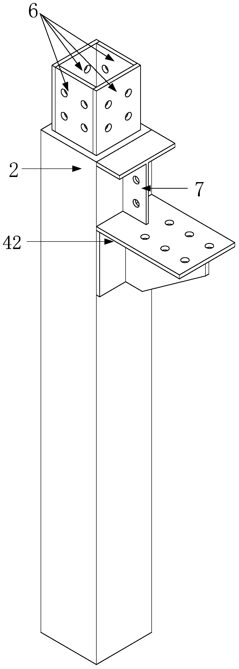
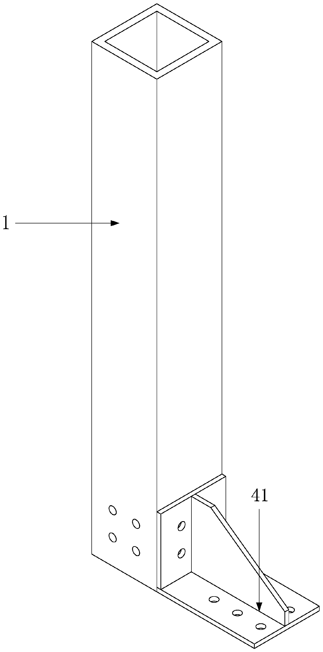
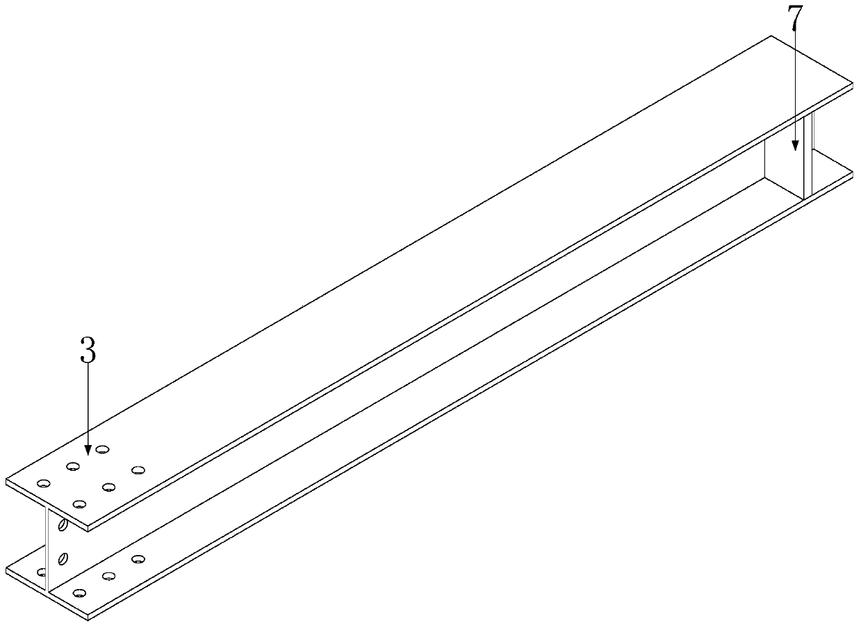
[0028] According to the present invention, a beam-to-column node of an assembled square steel structure with an interposer plate square steel pipe column splint connection includes: a lower column module A, an upper column module B, ...


PUM


Abstract

The invention discloses a beam column joint for connecting an assembling type steel structure inner inserting plate square steel pipe column clamping plate. The beam column joint comprises a lower column module, an upper column module, a beam module and a clamping plate. The lower column module is formed by welding a lower column, a rib carrier plate, an inner inserting plate and a stiffening ribin a factory. The upper column module is formed by welding an upper column and rib carrier plate in a factory. The beam module is formed by welding an H-shaped steel beam and the stiffening rib in thefactory. Holes are formed in the reserved portions of the upper column, the H-shaped steel beam, the inner inserting plate, the rib carrier plate and the clamping plate, and the upper column, the H-shaped steel beam, the inner inserting plate, the rib carrier plate and the clamping plate are transported to the site to be assembled through bolts. The rib carrier plates have a function of locatingthe H-shaped steel beam in the assembling process and bear some beam end bending moment to improve the bearing force of the joint. The inner inserting plate facilitates installing of the upper columnmodule and the lower column module, and the hoisting difficulty is reduced. By arranging the rib carrier plates and the clamping plate, the damaged portion is moved to the outside of the joint, and outward moving of plastic hinges is achieved. Full-bolt connection is adopted, no welding operation is carried out on the site, construction is facilitated, operation is convenient, the assembling speedis high, and the quality is ensured easily.

Description

technical field [0001] The invention relates to the technical field of structural engineering, in particular to a beam-column joint connected by a square steel pipe column splint of an assembled steel structure inner insert plate. Background technique [0002] The prefabricated steel structure has the characteristics of standardized design, factory manufacturing, assembly construction, decoration integration and information management, which can effectively reduce the labor intensity on the construction site and shorten the construction period. It is a green building with a full life cycle. There is no wet work, which can significantly reduce construction dust and dust, and significantly reduce the pollution caused by construction. Prefabricated steel structure buildings have become an important construction method in developed countries such as Europe, America and Japan, and are also a new source of contemporary Chinese architectural development. [0003] Prefabricated ste...

Claims


Application Information

Patent Timeline
IPC IPC(8): E04B1/24E04B1/58
CPCE04B1/2403E04B2001/2415E04B2001/2418E04B2001/2454
Inventor 刘学春王玥
Owner BEIJING UNIV OF TECH
Why Eureka
Try Eureka