Hydraulic quick linkage clamping mechanism

A clamping mechanism and fast technology, applied in the direction of metal processing equipment, grinding workpiece support, manufacturing tools, etc., can solve the problems that affect the accuracy of workpiece use, high use cost, and low work efficiency, so as to improve work efficiency and manufacture Low cost and long service life

Pending Publication Date: 2019-10-22
泰州荣生轴业制造有限公司
View PDF6 Cites 0 Cited by
  • Summary
  • Abstract
  • Description
  • Claims
  • Application Information

AI Technical Summary

Problems solved by technology

[0003] The purpose of the present invention is to provide a hydraulic fast linkage clamping mechanism to solve the problem that the existing clamps proposed in the above background technology have a high cost of use, and when clamping with excessive force, it will cause greater damage to the workpiece and affect the workpiece. The accuracy of the later use, and when the clamping is completed, multiple sets of component mechanisms are required for positioning and debugging, which makes the problem of low work efficiency

Method used


Image

  • Hydraulic quick linkage clamping mechanism
  • Hydraulic quick linkage clamping mechanism
  • Hydraulic quick linkage clamping mechanism

Examples


Embodiment 1

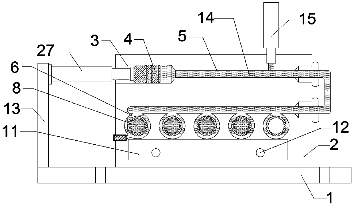
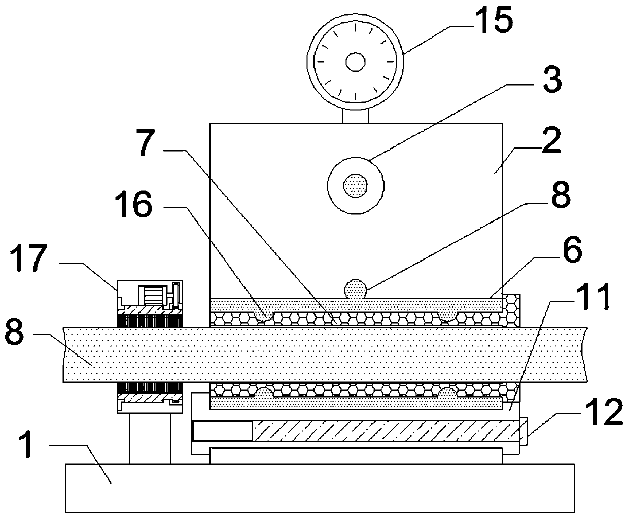
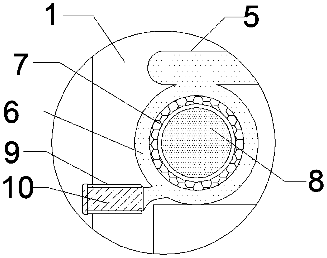
[0024] like Figure 1-6 As shown, a hydraulic fast linkage clamping mechanism includes a base 1, a clamp body 2 and an ash removal sleeve 17, the clamp body 2 is welded on the top side of the base 1, and a piston groove 3 is opened at the top end of the clamp body 2, The piston rod 4 is inserted in the piston groove 3, the liquid material pipe 5 is installed on one side of the piston groove 3 through the pipe groove, the piston groove 3 is connected with the liquid material pipe 5, and the inner bottom of the clamp body 2 is inserted Elastic deformation sleeve 6 is installed in the groove, elastic clamping sleeve 7 is inserted in the elastic deformation sleeve 6, workpiece 8 is inserted in the elastic clamping sleeve 7, one end of the liquid material pipe 5 is connected with the elastic deformation sleeve 6 in turn, The liquid material pipe 5 is filled with liquid plastic 14, the bottom of the elastic deformation sleeve 6 is inserted with a limit block 11, and the limit block ...

Embodiment 2

[0035] like Figure 1-6 As shown, a hydraulic fast linkage clamping mechanism includes a base 1, a clamp body 2 and a grinding sleeve, the clamp body 2 is welded on the top side of the base 1, and a piston groove 3 is opened at the top end of the clamp body 2. A piston rod 4 is inserted in the piston groove 3, and a liquid material pipe 5 is installed through a pipe groove on one side of the piston groove 3, and the piston groove 3 is connected through the liquid material pipe 5, and the inner bottom of the clamp body 2 is installed through a slot An elastic deformation sleeve 6, an elastic clamping sleeve 7 is inserted in the elastic deformation sleeve 6, a workpiece 8 is inserted in the elastic clamping sleeve 7, one end of the liquid material pipe 5 is connected with the elastic deformation sleeve 6 in sequence, and the The liquid material pipe 5 is filled with liquid plastic 14, the bottom of the elastic deformation sleeve 6 is inserted with a limit block 11, the limit blo...


PUM


Abstract

The invention discloses a hydraulic quick linkage clamping mechanism. The hydraulic quick linkage clamping mechanism comprises a base, a fixture body and a dust removal sleeve. The fixture body is welded to one side of the top of the base. One end of the internal top of the fixture body is provided with a piston groove. A piston rod is inserted in the piston groove. A liquid pipe is mounted on oneside of the piston groove through a pipe groove. The liquid pipe penetrates through the piston groove. The hydraulic quick linkage clamping mechanism realizes quick clamping, can improve the workingefficiency, can conduct clamping on multiple workpieces simultaneously, ensures that the workpieces keep undeformed under the action of clamping force through pressure clamping control and is long inservice life, low in manufacturing cost and superior in comprehensive performance.

Description

technical field [0001] The invention belongs to the technical field of clamps, and in particular relates to a hydraulic fast linkage clamping mechanism. Background technique [0002] The use cost of the existing fixture is relatively high, and when clamping with excessive force, it will cause great damage to the workpiece, which will affect the accuracy of the later use of the workpiece, and when the clamping is completed, multiple sets of component mechanisms are required for positioning and debugging, so that the work efficiency lower. Contents of the invention [0003] The purpose of the present invention is to provide a hydraulic fast linkage clamping mechanism to solve the problem that the existing clamps proposed in the above background technology have a high cost of use, and when clamping with excessive force, it will cause greater damage to the workpiece and affect the workpiece. The accuracy of the later use, and when the clamping is completed, multiple sets of c...

Claims


Application Information

Patent Timeline
Patent Type & Authority Applications(China)
IPC IPC(8): B24B41/06B24B55/06
CPCB24B41/067B24B55/06
Inventor 王国荣
Owner 泰州荣生轴业制造有限公司
Why Eureka
Try Eureka