
Communicating type electrolytic lead smelting pot and using method thereof

A lead melting and heating furnace technology, which is applied in the field of electrolytic lead, can solve problems such as limited furnace space, heat loss, and flame penetration, and achieve the effects of high safety, enlarged space, and effective use of heat

Active Publication Date: 2019-10-18
XINXIANG HUARUI POWER SUPPLY MATERIAL
View PDF28 Cites 0 Cited by
  • Summary
  • Abstract
  • Description
  • Claims
  • Application Information

AI Technical Summary

Problems solved by technology

[0004] In view of the above situation, in order to overcome the defects of the prior art, the present invention provides a connected electrolytic lead melting pot and its use method, which solves the problem of flame penetration and heat loss caused by the limited chamber space of the existing lead melting boiler

Method used


Image

  • Communicating type electrolytic lead smelting pot and using method thereof
  • Communicating type electrolytic lead smelting pot and using method thereof

Examples


Embodiment 1

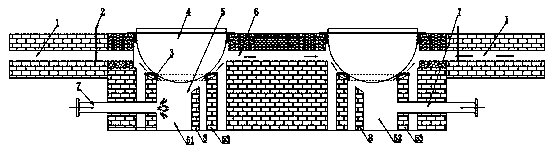
[0020] Embodiment one: by Figure 1 to Figure 2 Given, the connected electrolytic lead melting pot includes a heating furnace 5 and a lead melting pot 4 placed above the heating furnace, the heating furnace 5 is a furnace body with an upper opening, and the lead melting pot 4 is placed above the heating furnace 5 The opening of the heating furnace 5 includes a symmetrically placed first furnace body 51 and a second furnace body 52, and the first furnace body 51 and the second furnace body 52 are connected by a smoke pipe 6 Realize the interconnection between internal furnaces to form a connected boiler. The flame in the connected boiler circulates in the furnace of the first furnace body 51, the furnace connecting the smoke pipe 6 and the second furnace body 52, and each of the heating The side of the furnace 5 away from the connecting smoke pipe 6 is provided with a smoke exhaust pipe 1 for exhausting the flue gas. Since the first furnace body 51 and the second furnace body 5...

Embodiment 2

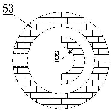
[0021] Embodiment 2: On the basis of Embodiment 1, the heating furnace 5 includes an outer furnace wall and an inner retaining wall, the outer furnace wall 53 is in the shape of a hollow cylinder, and the inner retaining wall 8 is smaller in diameter than the outer furnace wall A semi-circular arc-shaped wall with a diameter, the inner retaining wall 8 is located in the outer furnace wall to form an annular space for flue gas circulation, the combustion gun passes through the outer furnace wall, and the flame hits the annular inner retaining wall on the inner ring The curved surface is sunken inward, and returns to the direction close to the combustion gun under the action of the curved surface. The inner retaining wall 8 is lower than the outer furnace wall 53 and forms a smoke supply between the lead melting pot and the outer furnace wall. The gaps for air flow, thereby increasing the path of the flame of the combustion gun in the furnace, and fully utilizing the heat energy....


PUM


Abstract

The invention relates to the technical field of electrolytic lead, in particular to a communicating type electrolytic lead smelting pot and a using method thereof. An existing lead smelting pot has alimited-space combustion chamber, so that flame runs out of the furnace to cause heat loss. The communicating type electrolytic lead smelting pot comprises a heating furnace and a lead smelting pot body placed above the heating furnace; and the heating furnace comprises a first furnace body and a second furnace body which are symmetrically placed, the first furnace body communicates with the second furnace body through a connecting smoke pipe, smoke discharging pipes used for discharging smoke are arranged on the sides, away from the smoke pipe, of the heating furnace bodies, gate valves for controlling the smoke discharging pipes to be opened or closed are arranged at the ports, connected with the heating furnace bodies, of the smoke discharging pipes, combustion guns are arranged on thesides, close to the smoke discharging pipes, of the heating furnace bodies, and flame is combusted in the first heating furnace body with the corresponding smoke discharging pipe closed and then passes through the combustion chamber of the second heating furnace body. The heat is effectively utilized, and the communicating type electrolytic lead smelting pot has a good development prospect in thetechnical field of the electrolytic lead.

Description

technical field [0001] The invention relates to the technical field of electrolytic lead, in particular to a connected electrolytic lead melting pot and a use method thereof. Background technique [0002] Originally, in the production process of electrolytic lead and alloy lead, lead needs to be melted in a lead melting pot, and then gradually purified. Generally, two pots are required for operation, that is, copper impurities and other elements cannot be removed in the same pot. At the same time, in order to increase production and According to the technical requirements, two lead melting pots are required to be melted at the same time. [0003] The original lead smelting pot used a separate combustion gun and a separate flue. Because the interior space of the furnace is small, the flame can easily come out of the furnace directly. The chimney flame can penetrate more than 2 meters high, resulting in serious heat loss. Contents of the invention [0004] In view of the ab...

Claims


Application Information

Patent Timeline
Patent Type & Authority Applications(China)
IPC IPC(8): C22B13/02C22C1/02C25C1/18
CPCC22B13/02C22C1/02C25C1/18
Inventor 魏兴虎孙兵张冬雨张庆明曹太学陈永军
Owner XINXIANG HUARUI POWER SUPPLY MATERIAL
Learn More