
Design method of double-bias antenna auxiliary surface expansion curved surface for reducing noise temperature

A technology of noise temperature and surface design, applied in antennas, design optimization/simulation, computer-aided design, etc., can solve the problem of not giving the method of reducing noise temperature, not mentioning the design method of noise temperature, reducing the effective receiving area of ​​the antenna, etc. problem, to achieve the effect of reducing side lobe level, reducing edge leakage, and minimizing area

Active Publication Date: 2019-10-15
NO 54 INST OF CHINA ELECTRONICS SCI & TECH GRP
View PDF22 Cites 1 Cited by
  • Summary
  • Abstract
  • Description
  • Claims
  • Application Information

AI Technical Summary

Problems solved by technology

[0008] (1) No design related to noise and temperature
In the above three patents, it mainly involves the technology of antenna gain, side lobe and cross isolation, and does not mention the design method of noise temperature
[0009] (2) No method for reducing noise temperature is given
As we all know, the antenna quality factor is a very important technical indicator in the field of communication and radio astronomy. In the above patents, there is no method for how to reduce the noise temperature of the antenna.
[0010] (3) No bias method is given
Since this method is applied to a circularly symmetrical Cassegrain antenna, the flange added outside the secondary surface forms a shield in the direction of the antenna aperture, which reduces the effective receiving area of ​​the antenna, thus reducing the efficiency of the antenna
[0013] (2) Not suitable for dual-biased antennas
The method proposed in the book is only for Cassegrain-style antennas, not suitable for Gregorian-style double-biased antennas

Method used

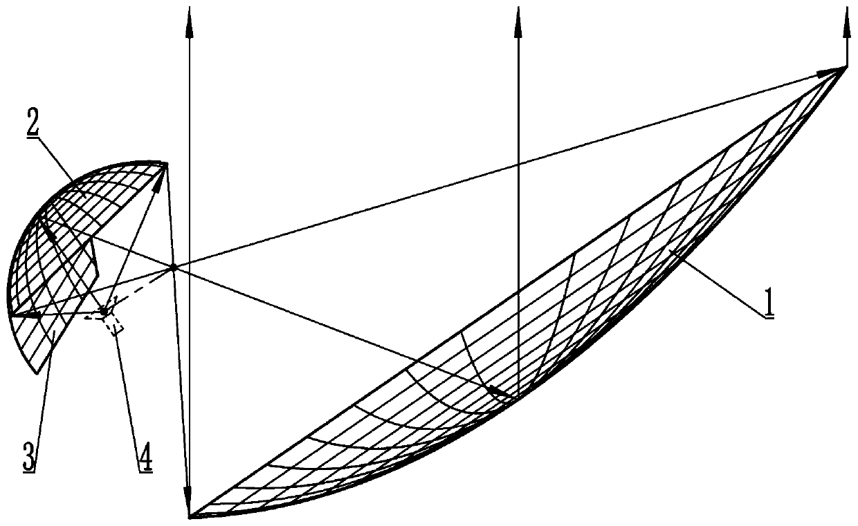
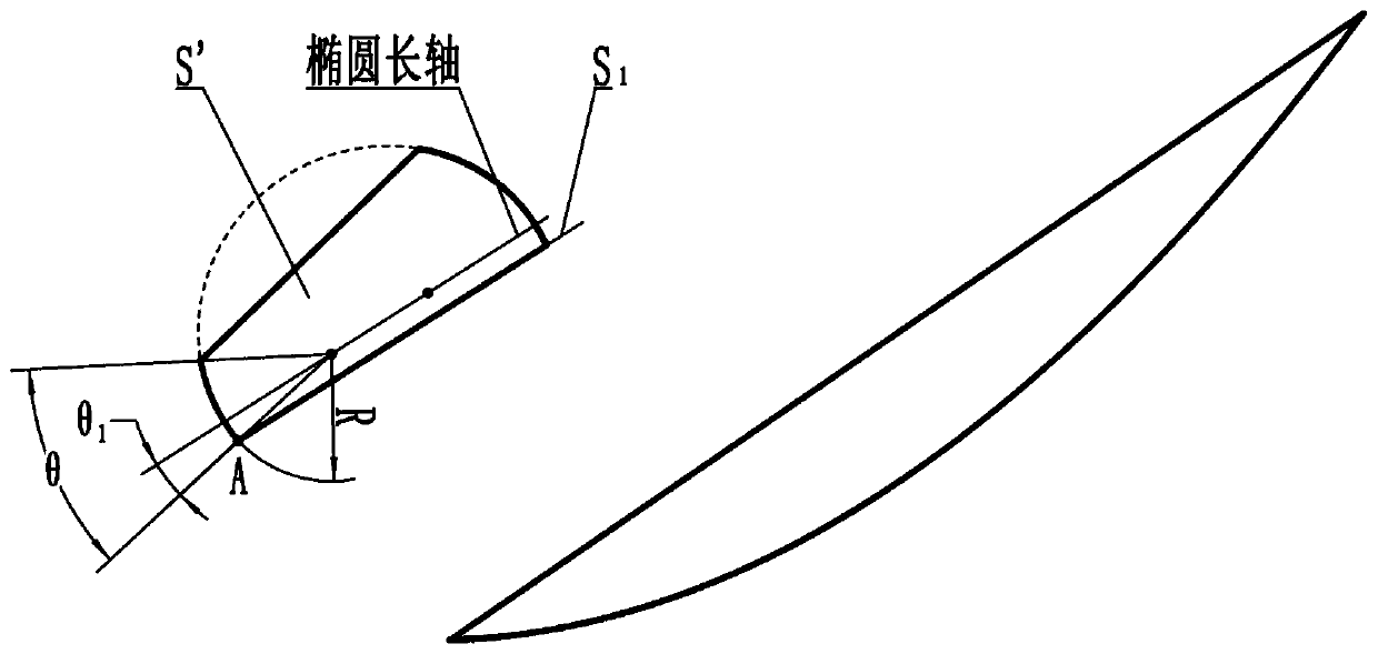

Image

  • Design method of double-bias antenna auxiliary surface expansion curved surface for reducing noise temperature
  • Design method of double-bias antenna auxiliary surface expansion curved surface for reducing noise temperature
  • Design method of double-bias antenna auxiliary surface expansion curved surface for reducing noise temperature

Examples


Embodiment Construction

[0063] The present invention will be further described below in conjunction with the accompanying drawings and specific embodiments.

[0064] This embodiment takes a dual-biased 15-meter aperture antenna as an example, and its structure is as follows figure 1 shown. The design method of the extended surface of the secondary surface in the embodiment includes the following steps:

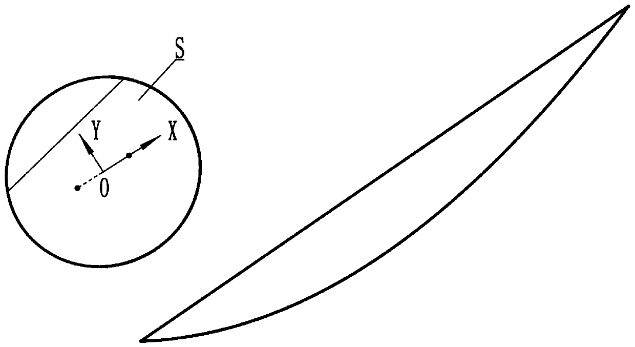
[0065] Such as figure 2 Shown:

[0066] (1) Take the line connecting the two foci of the sub-surface ellipse as the X axis, and the midpoint of the line as the coordinate origin, and establish a plane rectangular coordinate system XOY;

[0067] (2) In the coordinate system established in step (1), establish the ellipse equation:

[0068]

[0069] Among them, a is the semi-major axis of the sub-surface ellipse; b is the minor semi-axis of the sub-surface ellipse;

[0070] In the embodiment, a=3023.182mm, b=2873.497mm.

[0071] (3) Rotate the ellipse obtained in step (2) by 360 degrees around...


PUM


Abstract

The invention discloses a design method of a double-bias antenna auxiliary surface expansion curved surface for reducing noise temperature, and relates to the fields of communication, measurement andcontrol, radio astronomy and the like. According to the design method, the ellipsoid is obtained by rotating the minor ellipse, and then the ellipsoid is cut according to the parameters such as the feed source irradiation angle, the edge point coordinates and the minimum elevation angle of antenna work to form the extended curved surface. The extended curved surface reduces the edge diffraction ofelectromagnetic waves on the auxiliary surface and the leakage of feed source radiation, shields the thermal noise of the ground, increases the interception efficiency of the auxiliary surface, improves the gain of the antenna, improves the quality factor of the antenna, and is suitable for the design of antennas in the fields of radio astronomy, satellite communication, deep space exploration and the like.

Description

technical field [0001] The invention relates to the technical fields of communication, measurement and control, radio astronomy and the like, in particular to a method for designing a double-biased antenna subsurface extended curved surface for reducing noise temperature. Background technique [0002] The double-biased antenna means that the main plane is biased to the secondary plane, and the secondary plane is biased to the feed source. The double-biased antenna not only overcomes the shielding of the main surface of the secondary plane, but also overcomes the shielding of the secondary plane by the feed source and the support arm, thereby improving the near-axis side lobe characteristics of the antenna pattern and the input VSWR of the feed source characteristics, and has high antenna efficiency. [0003] The Gregorian double-biased antenna is easy to achieve a compact structure and has a large distance between the primary feed and the secondary surface, which can redu...

Claims


Application Information

Patent Timeline
Patent Type & Authority Applications(China)
IPC IPC(8): G06F17/50H01Q15/14H01Q15/16H01Q19/19
CPCH01Q15/141H01Q15/16H01Q19/19G06F30/20
Inventor 刘国玺杨文宁杜彪伍洋刘胜文宁晓磊杨晋蓉陈隆
Owner NO 54 INST OF CHINA ELECTRONICS SCI & TECH GRP
Learn More