
Ultrasonic Lamb wave defect signal recognition method based on variational mode decomposition

A technology of variational mode decomposition and ultrasonic Lamb wave, applied in the field of signal processing, can solve the problems of variational mode decomposition K value is difficult to determine, false components, mode mixing, etc., to solve the problem of mode mixing The effect of solving the problem of false components and improving the accuracy and recognition rate

Active Publication Date: 2019-10-15
DALIAN OCEAN UNIV
View PDF37 Cites 10 Cited by
  • Summary
  • Abstract
  • Description
  • Claims
  • Application Information

AI Technical Summary

Problems solved by technology

[0006] The present invention mainly solves the technical problems such as the difficult determination of the K value in the variational mode decomposition in the prior art, which leads to mode aliasing and generation of false components, and the inability to accurately detect defect signals, etc., and proposes an ultrasonic Lamb Ultrasonic wave defect signal identification method, so as to achieve the purpose of accurately identifying ultrasonic Lamb wave defect signal

Method used


Image

  • Ultrasonic Lamb wave defect signal recognition method based on variational mode decomposition
  • Ultrasonic Lamb wave defect signal recognition method based on variational mode decomposition
  • Ultrasonic Lamb wave defect signal recognition method based on variational mode decomposition

Examples


Embodiment 1

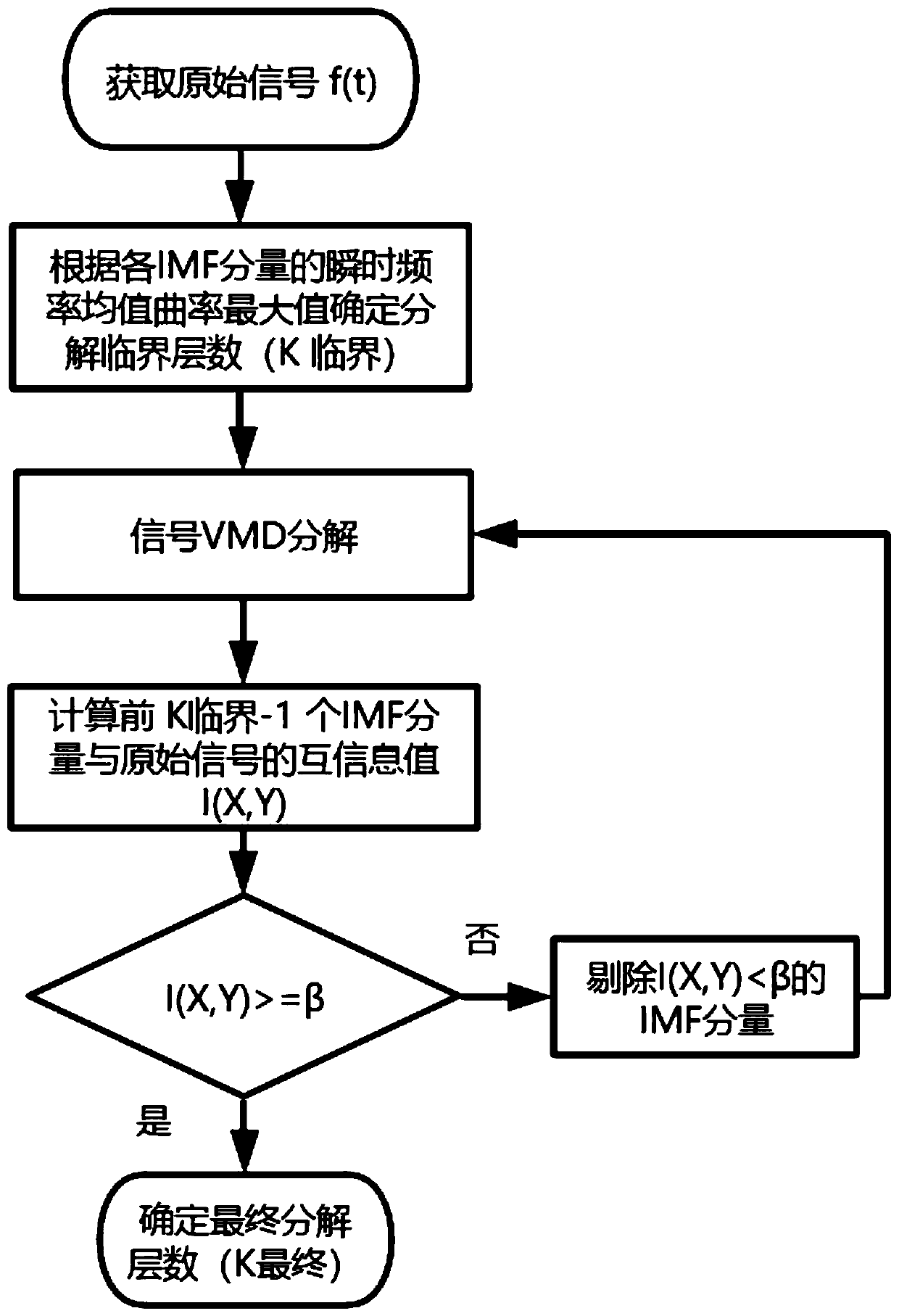
[0046] figure 1 It is a flow chart of realizing the ultrasonic Lamb wave defect signal identification method based on variational mode decomposition provided by the present invention. Such as figure 1 As shown, the method for identifying ultrasonic Lamb wave defect signals based on variational mode decomposition provided by the embodiment of the present invention includes:

[0047] Step 1: Use the signal generator to generate excitation signals to detect the aluminum plate, and the receiving transducer on the other side of the aluminum plate receives the original signal of the ultrasonic Lamb wave.

[0048] The signal generator generates an excitation signal, and the excitation signal is amplified by the power amplifier to excite the aluminum plate to be detected, and the ultrasonic Lamb wave is generated and propagated in the aluminum plate to be detected, and the ultrasonic Lamb wave will reflect and scatter when it passes through a defect on the aluminum plate. The echo s...

Embodiment 2

[0088] The ultrasonic Lamb wave defect signal identification method based on variational mode decomposition provided by the embodiment of the present invention includes:

[0089] Step 1: Use a signal generator to generate an excitation signal to detect the aluminum plate, and receive the original signal of the ultrasonic Lamb wave at the receiving transducer on the other side of the aluminum plate.

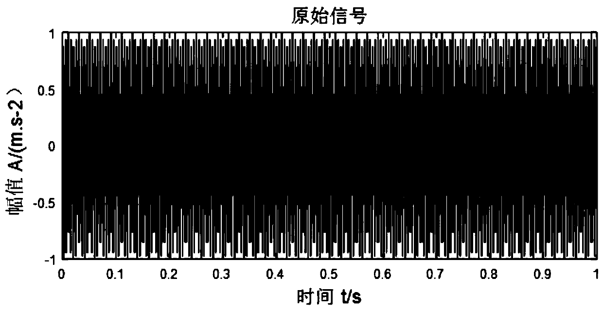
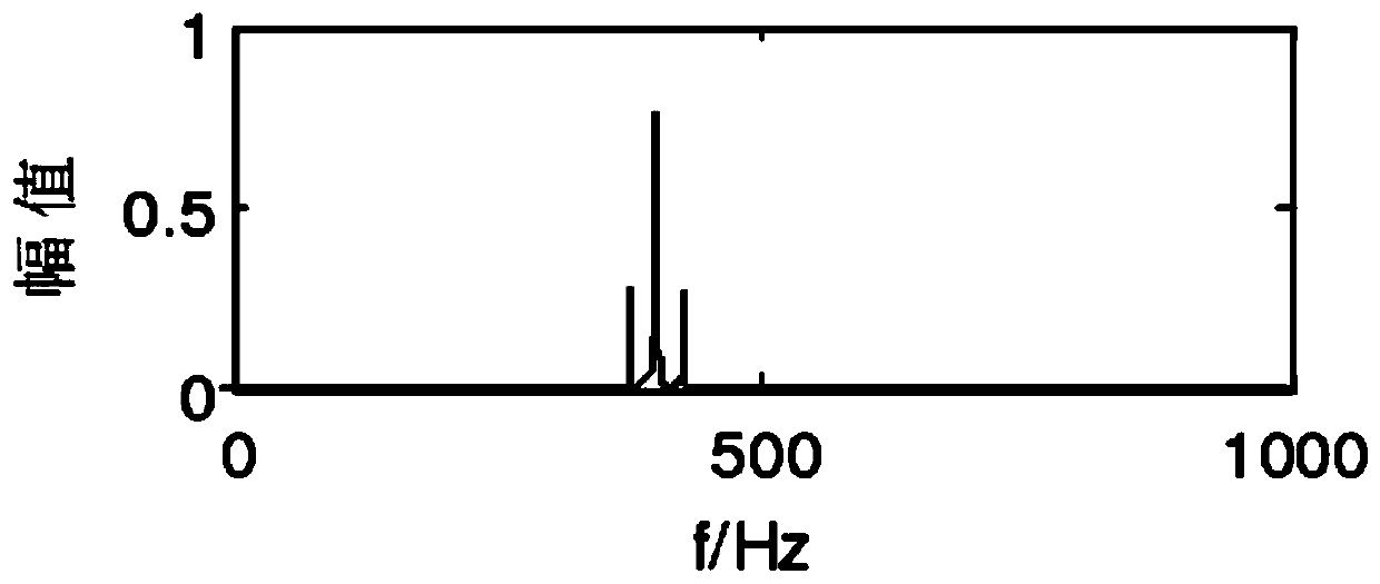
[0090] According to the frequency characteristics of the ultrasonic Lamb wave signal, this example adopts the frequency modulation signal: f=cos(2*pi*400*t+0.5cos(2*pi*25*t)), the signal acquisition sampling frequency is 10k Hz, and the frequency modulation The signal mainly includes three frequency components: 400Hz main frequency, 375Hz and 425Hz sidebands. The time domain waveform of the signal is as figure 2 As shown, the frequency domain waveform is as image 3 shown.

[0091] Step 2, according to the obtained original signal f(t) of the ultrasonic Lamb wave, determine th...

Embodiment 3

[0102] The ultrasonic Lamb wave defect signal identification method based on variational mode decomposition provided by the embodiment of the present invention includes:

[0103] Step 1: Use a signal generator to generate an excitation signal to detect the aluminum plate, and receive the original signal of the ultrasonic Lamb wave at the receiving transducer on the other side of the aluminum plate.

[0104] Obtain the original signal f(t) of ultrasonic nondestructive testing, and the time domain waveform of the signal is as follows Figure 14 As shown, the signal sampling time is 1ms, the number of sampling points is 700, and the signal excitation frequency is 120kHz.

[0105] Step 2, according to the obtained original signal f(t) of the ultrasonic Lamb wave, determine the input parameters of the variational mode decomposition.

[0106] α=2000, ε=1e-7. The number of decomposition layers K of VMD is an important factor affecting the final decomposition effect. If the K value ...


PUM


Abstract

The present invention relates to the technical field of signal processing, and provides an ultrasonic Lamb wave defect signal recognition method based on variational mode decomposition, including: step 1, exciting a to-be-detected aluminum plate by using an excitation signal to obtain a raw signal of an ultrasonic Lamb wave; step 2, determining an input parameter for variational mode decompositionaccording to the obtained raw signal of the ultrasonic Lamb wave; step 3, performing variational mode decomposition according to the determined input parameter for variational mode decomposition; step 4, calculating mutual information values between K<critical>-1 IMF components and the raw signal, comparing the mutual information values with a mutual information threshold, considering the IMF components for which the mutual information value is less than the mutual information threshold as false components and removing the false components, determining a final K value and in turn determiningthe number of final decomposition layers; and step 5, after determining the final number of decomposition layers, performing defect identification by using the obtained defect signal of a center frequency. The method enables accurate identification of a defect signal of the ultrasonic lamb wave.

Description

technical field [0001] The invention relates to the technical field of signal processing, in particular to an ultrasonic Lamb wave defect signal identification method based on variational mode decomposition. Background technique [0002] As a nonlinear and non-stationary signal, the ultrasonic detection signal itself contains many mutations. In addition to the complexity of the structure of the detection equipment, it cannot simply use the processing method suitable for stationary signals. The time-domain and frequency-domain processing and analysis of ultrasonic defect signals is still a very complicated subject. The ultrasonic defect signals collected in the experiment often have a lot of noise, which has a great impact on signal processing and feature analysis, and the feature description of various defects is not clear. Qualitative criteria, the signals for similar defects tend to be similar. Therefore, in ultrasonic nondestructive testing, it is necessary to process th...

Claims


Application Information

Patent Timeline
IPC IPC(8): G01N29/00G01N29/44
CPCG01N29/00G01N29/4427G01N29/4454G01N29/4472G01N2291/0289G01N2291/0427
Inventor 李松松张宸宸夏闻泽郭中会向宽赵斯琪李敏
Owner DALIAN OCEAN UNIV
Learn More