
Material recycling system

A technology for recycling systems and materials, applied in pipeline systems, cleaning hollow objects, chemical instruments and methods, etc., can solve the problems of complex pressure relief structure, product fallback, and high cost, and achieve simple overall structure, simple assembly and use, and recycling. Efficient effect

Pending Publication Date: 2019-10-15
齐力控股集团有限公司
View PDF1 Cites 1 Cited by
  • Summary
  • Abstract
  • Description
  • Claims
  • Application Information

AI Technical Summary

Problems solved by technology

[0005] The above-mentioned product recovery system can solve the problem of viscous medium sticking to the inner wall of the pipeline and being wasted, but there are still the following technical problems: the rubber ball needs to be separated from the pipeline during pressure relief to allow the high-pressure gas to be discharged, which makes the pressure relief structure complicated and requires two Positioning valves and jigs for clamping rubber balls are costly, and products that do not enter the connecting pipeline of the filling machine but are still in the receiving pipeline will fall back into the delivery pipeline, resulting in waste

Method used


Image

  • Material recycling system
  • Material recycling system
  • Material recycling system

Examples


Embodiment Construction

[0049] The present invention will be described in further detail below in conjunction with the accompanying drawings.

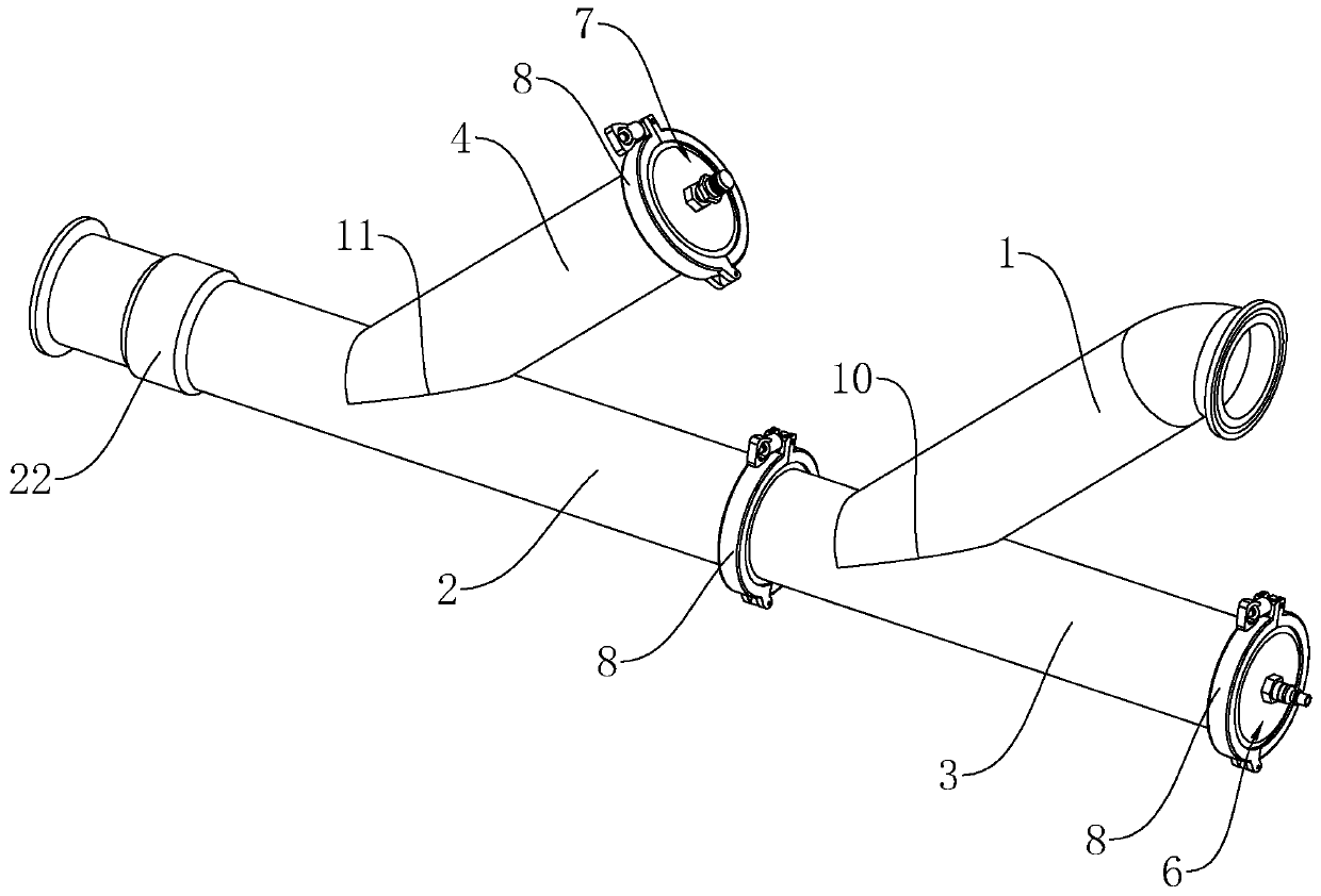
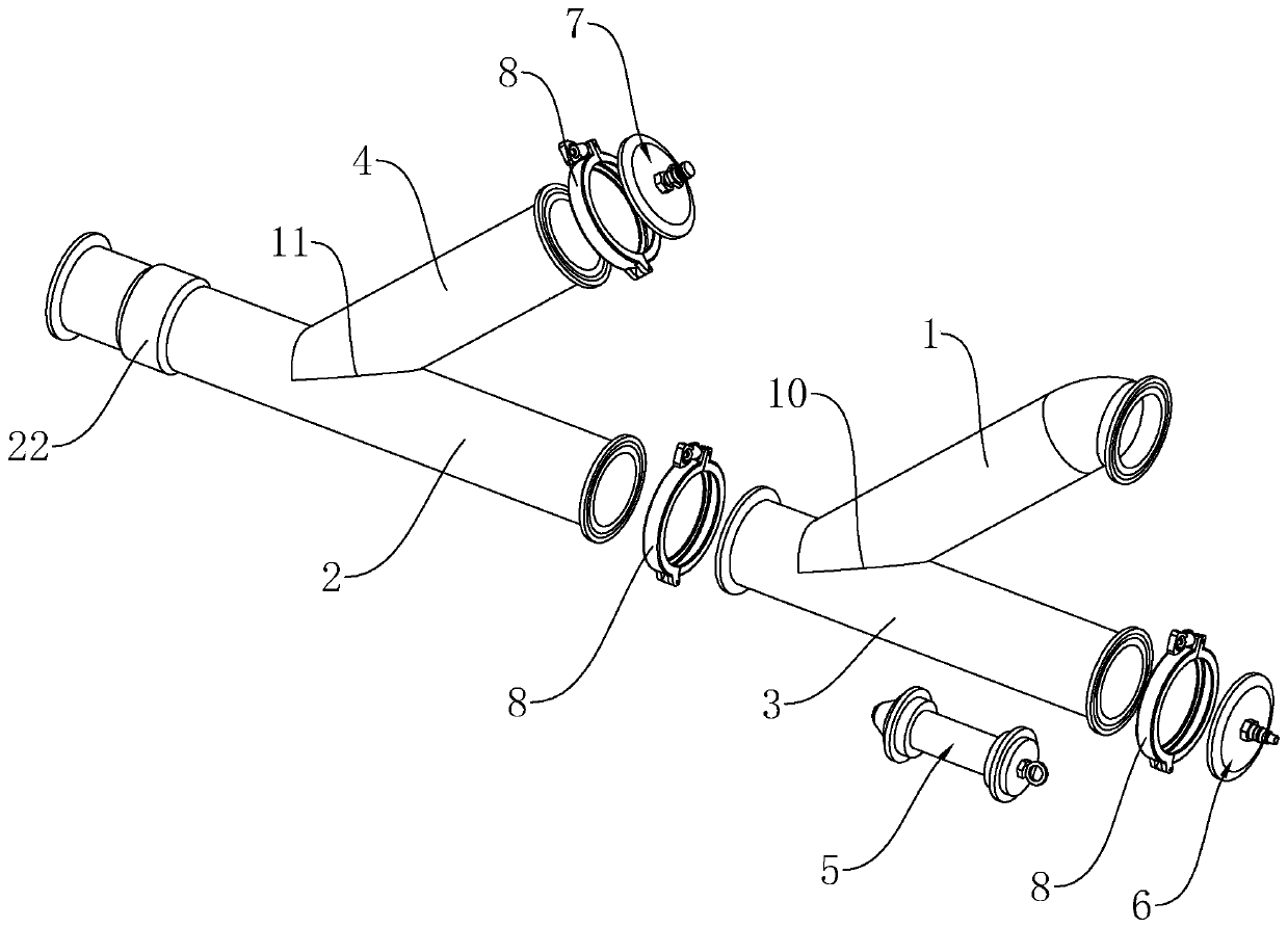
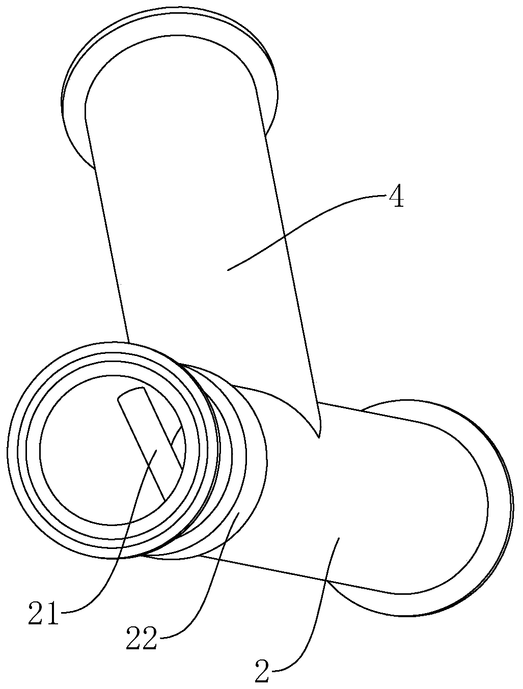
[0050] A material recovery system such as figure 1 , 2 As shown, it includes the feed pipe 1 for the material to enter, the discharge pipe 2 for the material to move out, the cleaner 5 for cleaning the material on the inner wall of the pipe, the launch pipe 3 for the cleaner 5 to be preset, and the gas to enter the pipe to push The intake device 6 for the movement of the cleaner 5, and the pressure relief pipe 4 and the pressure relief device 7 for discharging the gas in the pipe.

[0051] Such as figure 1 , figure 2 As shown, the feed pipe 1 is fixedly connected to one side of the launch pipe 3 and the connection is a feed position 10, and the launch pipe 3 and the discharge pipe 2 are directly connected by a clamp 8 or at least one intermediate joint is connected by a clamp 8. pipeline (not shown in the figure). The intermediate pipe can be pipe fitti...


PUM


Abstract

The invention discloses a material recycling system, and relates to the field of pipeline conveying. According to the technical scheme, the material recycling system comprises a feeding pipeline and adischarging pipeline, and further comprises an emission pipeline, a cleaner, an air inlet device, a pressure relief pipeline and a pressure relief device, and the emission pipeline and the discharging pipeline are directly connected through a hoop or are connected through at least one middle pipeline through hoops; the feeding pipeline is connected to one side of the emission pipeline, the connecting position between the feeding pipeline and the emission pipeline is a feeding position, the air inlet device is arranged at the end, away from the discharging pipeline, of the emission pipeline, and the cleaner is arranged between the feeding position and the air inlet device and is tightly attached to the inner wall of the emission pipeline; and the pressure relief pipeline is connected to one side of the discharging pipeline, the connecting position the pressure relief pipeline and the discharging pipeline is the pressure relief position, the pressure relief device is arranged at the end, away from the discharging pipeline, of the pressure relief pipeline, and a stop rod used for blocking the cleaner is connected to the inner wall of the end, away from the emission pipeline, of the discharging pipeline. The system is simple in overall structure, convenient to install and high in material recovery efficiency.

Description

technical field [0001] The invention relates to the field of pipeline transportation, in particular to a material recovery system. Background technique [0002] Pipes are devices connected by pipes, pipe connectors and valves to transport gases, liquids or fluids with solid particles. They are commonly used in various industries, such as the transportation of domestic water, municipal sewage, and chemical raw materials. For food and other industries, some conveying media are highly viscous, such as: sauces, yogurt, etc., which are easy to adhere to the pipe wall during the conveying process, resulting in waste of materials, and a large amount of water and detergent are needed after each production is completed. Pipes cleaned. [0003] The Chinese patent with the publication number CN109442220A discloses a product recovery system, including a first reversing valve, a shut-off valve, a positioning valve a, a positioning valve b, a launch valve, a medium inlet a for pushing th...

Claims


Application Information

Patent Timeline
Patent Type & Authority Applications(China)
IPC IPC(8): F17D1/00B08B9/055
CPCF17D1/00B08B9/055Y02W30/62
Inventor 朱常有
Owner 齐力控股集团有限公司
Learn More