Metallurgical apparatus

The technology of metallurgical equipment and mixing box, which is applied in the field of metallurgical processing, can solve the problems of heavy workload of operators, inconvenient dumping of raw materials, low work efficiency, etc., and achieves the effects of convenient operation, simple structure and improved feeding speed.

Inactive Publication Date: 2019-10-15
余颖
View PDF0 Cites 0 Cited by
  • Summary
  • Abstract
  • Description
  • Claims
  • Application Information

AI Technical Summary

Problems solved by technology

[0003] The existing powder metallurgy production process generally prepares powder particles of suitable particle size first, then presses them into shape, and then sinters them to form parts with fixed shapes. The density and product performance after sintering are directly related to the size of powder particles. The requirements of the products are different. Powder particles of different particle sizes need to be uniformly mixed in different proportions to achieve the desired effect. It needs to be stirred and mixed by a mixer. However, the existing feeding device for powder metallurgy is not very convenient. When transporting raw materials, It is easy to cause raw materials to flutter while operating at high altitude, and it is very inconvenient to dump raw materials. Once the phenomenon of pouring occurs in high altitude, it is difficult to deal with and the process is cumbersome. In this way, the workload of operators is heavy. , low work efficiency

Method used


Image

  • Metallurgical apparatus
  • Metallurgical apparatus
  • Metallurgical apparatus

Examples


Embodiment 1

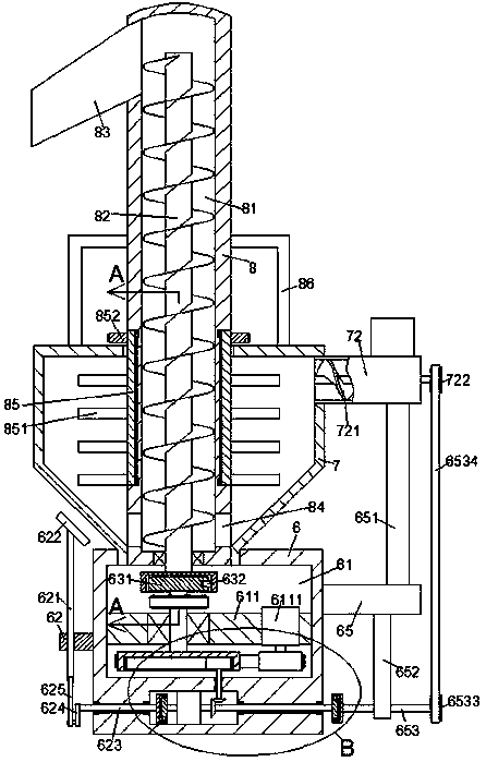
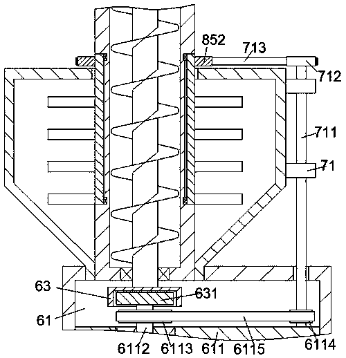
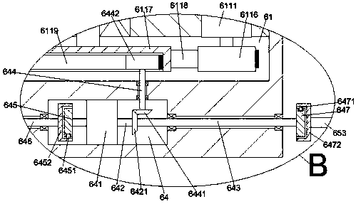
[0023] The rotation of the fifth pulley 6116 is controlled by the driving motor 6111, and the fourth pulley 6117 is driven by the first transmission belt 6118 on the fifth pulley 6116 to rotate. The pulley 6113 rotates, and the fourth pulley 6117 drives the driving gear 6442 and the second bevel gear 6441 at the bottom of the fifth rotating shaft 644 to rotate. At the same time, the second transmission belt 6115 on the third pulley 6113 drives the sixth pulley 6114 At the same time, the third pulley 6113 drives the first ratchet part 632 on the first disc 631 to slide and fit with the inner teeth in the first inner ratchet disc 63, so that the first inner ratchet disc 63 and the first inner ratchet disc 63 The first screw rod 82 is in a static state. At this time, due to the rotation of the sixth pulley 6114, the second rotating shaft 711 and the seventh pulley 712 at the top of the second rotating shaft 711 are driven to rotate. At this time, the seventh pulley 712 The third ...

Embodiment 2

[0025] The fifth pulley 6116 is controlled to rotate in reverse by the driving motor 6111, and then the first transmission belt 6118 on the fifth pulley 6116 drives the fourth pulley 6117 to rotate in reverse. At this time, the fourth pulley 6117 drives the first The third pulley 6113 at the top of the rotating shaft 6112 rotates in reverse, and the fourth pulley 6117 drives the driving gear 6442 and the second bevel gear 6441 at the bottom of the fifth rotating shaft 644 to rotate in reverse. The second transmission belt 6115 drives the sixth pulley 6114 to rotate in reverse, and at the same time, the third pulley 6113 drives the first disc 631 to rotate in reverse, so that the first ratchet 632 on the first disc 631 is aligned with the first inner The ratchet disc 63 works together, and then the first inner ratchet disc 63 drives the first screw rod 82 to rotate. The rotation of the screw rod 82 makes the material transfer to the discharge port 83 to realize the automatic co...


PUM


Abstract

The invention discloses a metallurgical apparatus. The metallurgical apparatus comprises a driving cabinet, a mixing box arranged at the top of the driving cabinet, and a material conveying pipeline fixedly arranged in the mixing box and extending upwards, the top extension segment of the material conveying pipeline extends out of the top end surface of the mixing box, a transmission chamber is arranged in the material conveying pipeline, the transmission chamber is in internal rotating fit connection with a first screw rod, the outer surface of the material conveying pipeline is in rotating fit connection with a rotating sleeve extending up and down, the top segment of the rotating sleeve extends out of the top end surface of the mixing box and is circumferentially fixedly provided with afirst belt wheel, the bottom segment of the rotating sleeve is located in the mixing box, and the outer surface of the bottom segment of the rotating sleeve is circumferentially fixedly provided with a plurality of sets of equidistantly arranged stirring blades. The apparatus has the advantages of simple structure, convenience in operation, improvement of the mixing efficiency and the mixing quality, clogging prevention, time and labor saving, and improvement of the overall feeding speed.

Description

technical field [0001] The invention relates to the technical field of metallurgical processing, in particular to metallurgical equipment. Background technique [0002] With the growing economy of our country, new technologies and new materials are constantly emerging, and powder metallurgy materials are one of them. Powder metallurgy can produce porous, semi-dense or fully dense parts, such as oil-impregnated bearings, gears and other parts, which are widely used in various industries. [0003] The existing powder metallurgy production process generally prepares powder particles of suitable particle size first, then presses them into shape, and then sinters them to form parts with fixed shapes. The density and product performance after sintering are directly related to the size of powder particles. The requirements of the products are different. Powder particles of different particle sizes need to be uniformly mixed in different proportions to achieve the desired effect. I...

Claims


Application Information

Patent Timeline
IPC IPC(8): B01F7/18B01F15/02B22F1/00
CPCB22F1/0003B01F27/191B01F27/90B01F35/71705B01F35/71B01F35/75455B01F35/75
Inventor 余颖
Owner 余颖
Why Eureka
Try Eureka