
Paster radiation unit

A radiating unit and patch technology, which is applied in the structural form of radiating elements, electrical components, antennas, etc., can solve the problems of inability to realize mobile communication broadband, ultra-wideband requirements, relatively narrow frequency band, low power capacity, etc., to achieve performance optimization, The effect of widening the working bandwidth and improving the power capacity

Active Publication Date: 2019-10-11
PROSE TECH CO LTD
View PDF12 Cites 2 Cited by
  • Summary
  • Abstract
  • Description
  • Claims
  • Application Information

AI Technical Summary

Problems solved by technology

However, the existing patch antennas have the following problems: 1. Generally, the relatively narrow frequency band and large size cannot meet the broadband and ultra-wideband requirements of current mobile communications. 2. Most patch antennas only radiate to half space. 3. , Generally printed on a high dielectric substrate, there may be surface waves, and the power capacity is low

Method used


Image

  • Paster radiation unit
  • Paster radiation unit
  • Paster radiation unit

Examples


Embodiment Construction

[0032] The technical solutions of the embodiments of the present invention will be clearly and completely described below in conjunction with the accompanying drawings of the present invention.

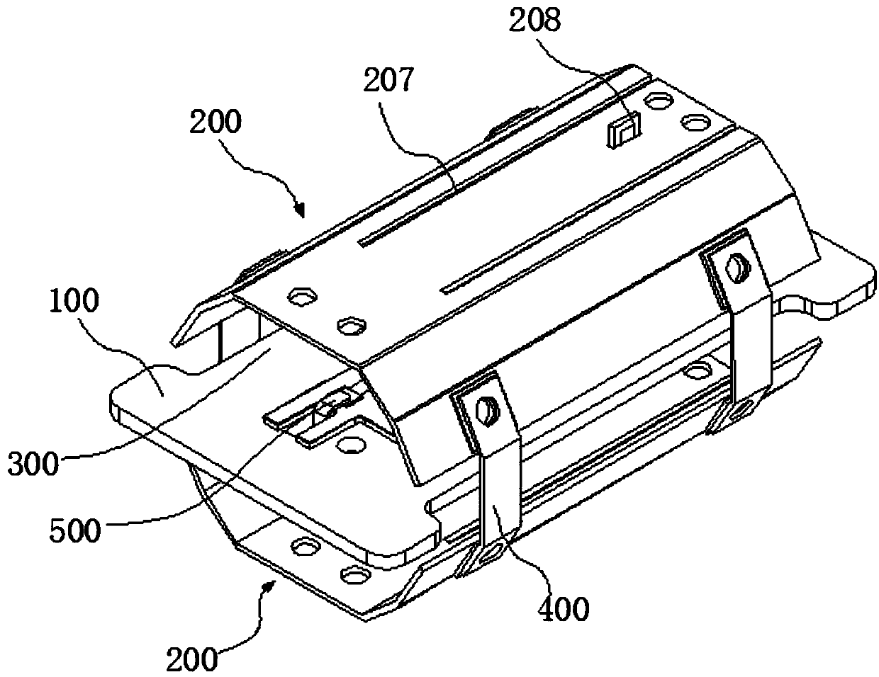
[0033] A patch radiating unit disclosed by the present invention adopts a conformal curved surface and a grooved surface structure, which can effectively widen the working bandwidth of the antenna under the premise of reducing the width of the radiating unit, and can meet the broadband demand.

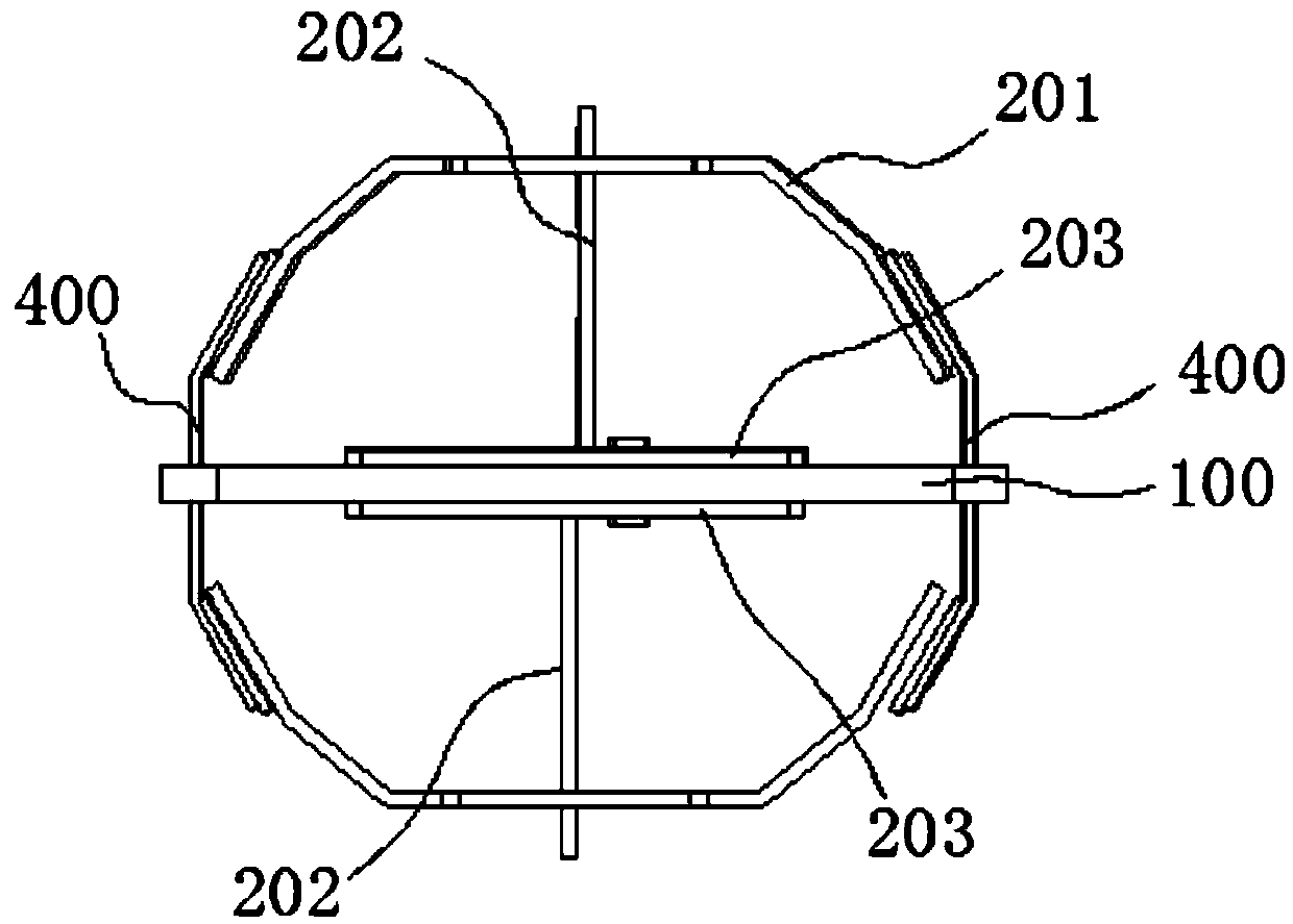
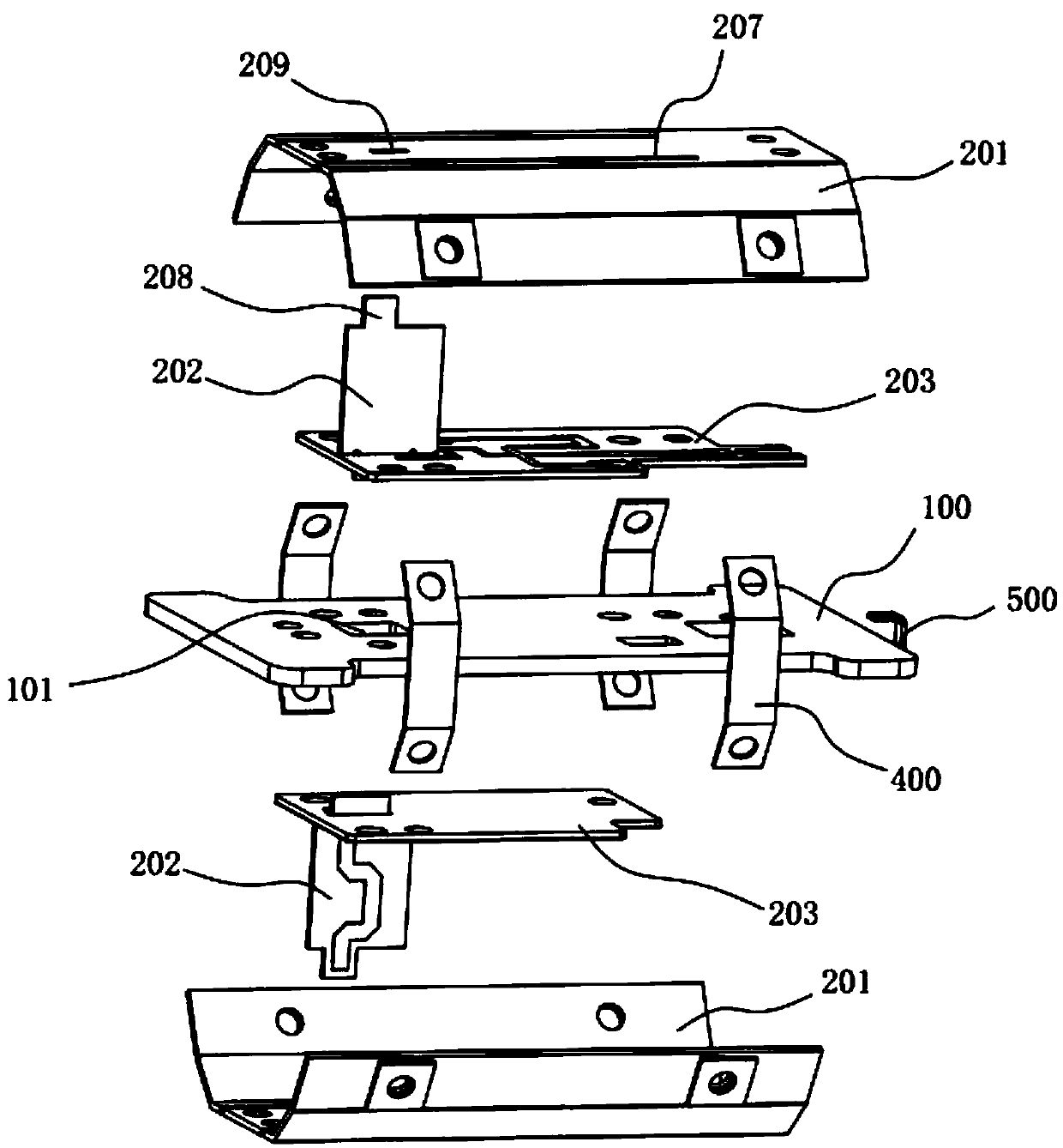
[0034] combine Figure 1 ~ Figure 3 As shown, a patch radiation unit disclosed in the embodiment of the present invention includes a reflector 100 and two radiation units 200 symmetrically installed on the front and back sides of the reflector 100, and each radiation unit 200 includes a radiation patch 201 , the feeding balun 202 and the matching network 203 , the radiation patch 201 is electrically connected to the matching network 203 through the feeding balun 202 , and the matching network ...


PUM


Abstract

The invention discloses a patch radiation unit. The patch antenna unit comprises a reflection plate and a radiation unit installed on one side surface of the reflection plate. The radiation unit comprises a radiation patch, a feed balun and a matching network, wherein the radiation patch is electrically connected with the matching network through the feed balun, the matching network is fixed on the reflection plate, the radiation patch is of a curved surface structure arched in the direction away from the reflection plate, and at least one slot line is formed in the radiation patch. By adopting a curved surface conformal and surface slotted structure, the working bandwidth of an antenna can be effectively broadened on the premise of reducing the width of the radiation unit.

Description

technical field [0001] The invention relates to the field of mobile communication and is applied to an antenna network system, in particular to a patch radiation unit used as a base station antenna. Background technique [0002] With the rapid development of the communication industry, the requirements for antenna performance are getting higher and higher. The antenna is required to have good pattern characteristics in a limited space and a wide frequency band. So the current research focus is on broadband, miniaturization and so on. [0003] Among them, the microstrip antenna has a series of advantages such as small size, light weight, low cost, and easy integration. It has unique features in miniaturized antennas, so it has been widely used since it came out. However, the existing patch antennas have the following problems: 1. Generally, the relatively narrow frequency band and large size cannot meet the broadband and ultra-wideband requirements of current mobile communi...

Claims


Application Information

Patent Timeline
Patent Type & Authority Applications(China)
IPC IPC(8): H01Q1/36H01Q1/50H01Q19/10H01Q21/29
CPCH01Q1/50H01Q19/104H01Q1/38H01Q21/06H01Q21/0006Y02D30/70
Inventor 董志峰孙静张妍
Owner PROSE TECH CO LTD
Learn More