
Double cabin structures for multi-purpose helicopter

A technology for helicopters and cabins, applied to vertical take-off and landing aircraft, wings, fuselages, etc., can solve problems such as complex maintenance, limited helicopters, and easy wear and tear of working methods

Pending Publication Date: 2019-10-11
刘保伸 +3
View PDF10 Cites 2 Cited by
  • Summary
  • Abstract
  • Description
  • Claims
  • Application Information

AI Technical Summary

Problems solved by technology

[0003] 1. Traditional helicopters have been criticized by the public for not being able to escape easily into flying coffins
[0004] 2. The layout of the center of gravity of traditional helicopters is constrained by the driver's seat and control equipment, and cannot be better arranged, resulting in restrictions on the load space and load position
[0005] 3. In order to balance the center of gravity, the traditional helicopter cannot make a more reasonable distribution design for the carrying weight more effectively
[0006] 4. The hammer-like flight trajectory of traditional helicopters is also relatively inflexible
[0007] 5. Traditional helicopters are also limited by their structure and cannot design more solutions that can overcome the torque of the main rotor
[0008] 5. Traditional helicopters are limited by traditional structures and cannot design higher-speed flight structures
[0014] 12. For the traditional mechanical rotor, its limited and complex mechanical structure and its working method are not only prone to wear and tear, but also affect the service life, and are easily affected by the environment, and its maintenance is also complicated.

Method used


Image

  • Double cabin structures for multi-purpose helicopter
  • Double cabin structures for multi-purpose helicopter
  • Double cabin structures for multi-purpose helicopter

Examples


Embodiment Construction

[0236] In the following, the technical means adopted by the present invention to achieve the intended purpose of the invention will be further described in conjunction with the accompanying drawings and preferred embodiments of the present invention.

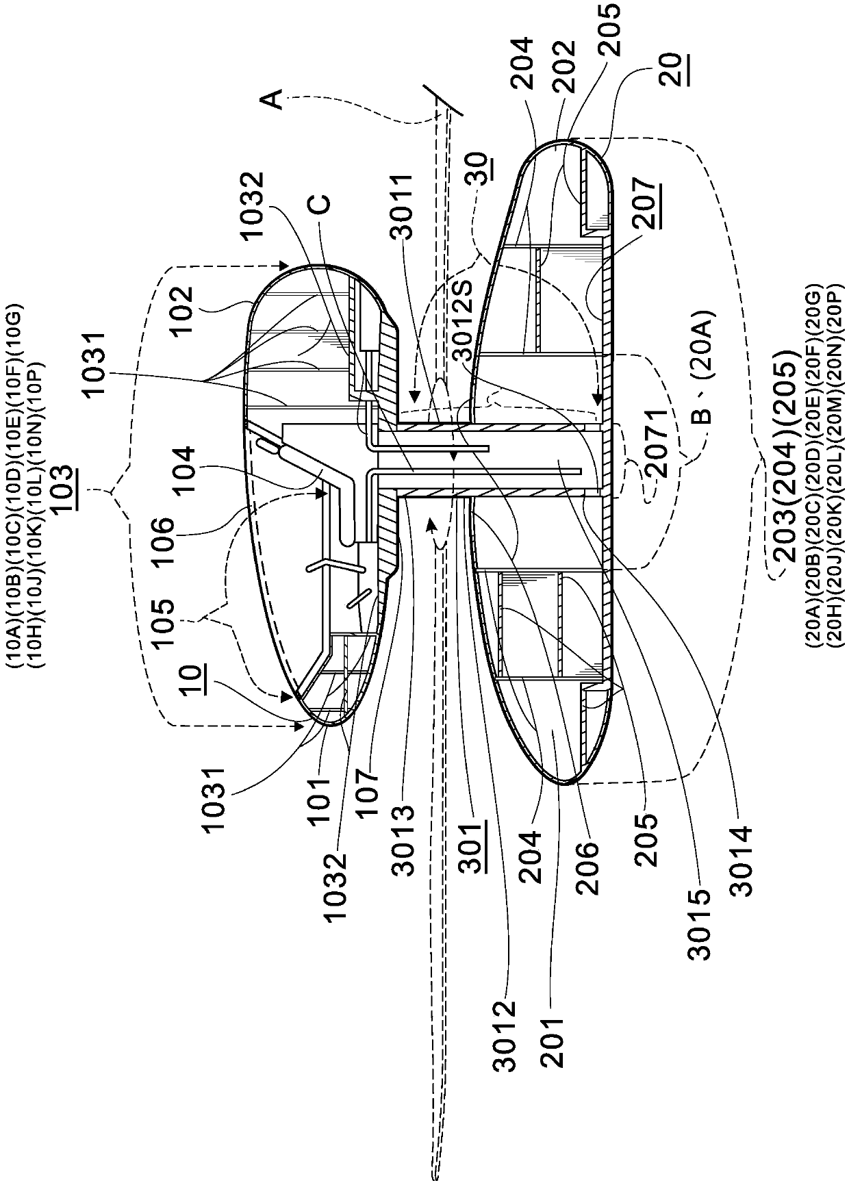
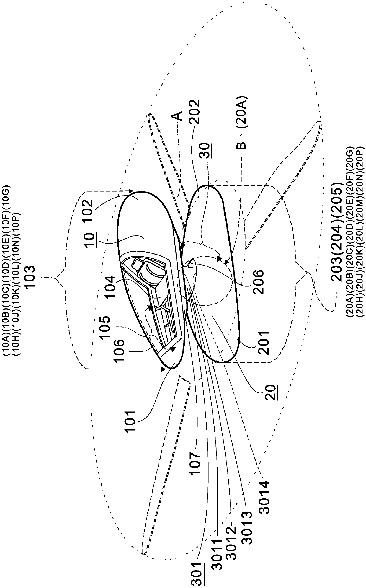
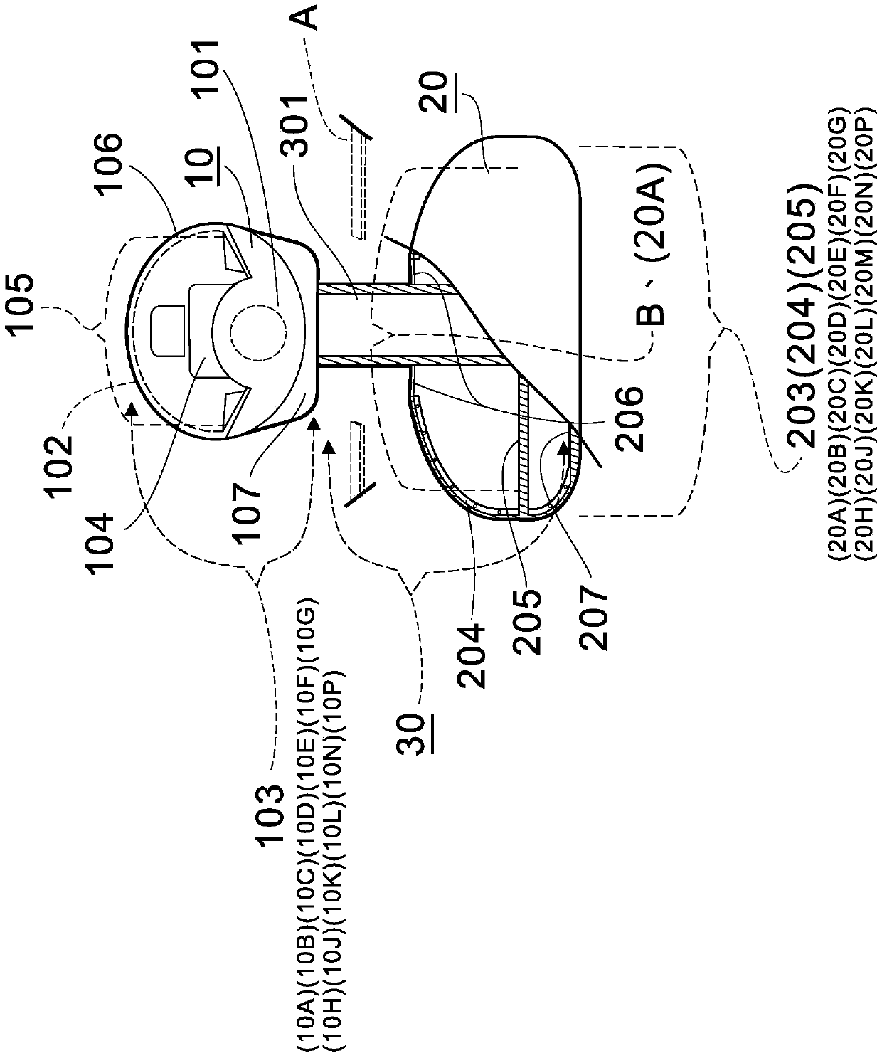
[0237] Referring to shown in Fig. 1 (with reference to Fig. 2 to No. 3), (the present invention) first embodiment; Comprise an upper cabin 10, lower cabin 20, a central rotor position 30;

[0238] An upper engine room 10, which is two ends 101, 102 and has a shell 103 (the material of the shell 103 can be selected from metal, plastic, carbon fiber, metal or plastic compound, and various nano-scale materials with the ability to isolate foreign objects or support pressure) Available materials are used as skin shells), enough to provide driver's seat 104 or control equipment and intelligent microprocessor and fly-by-wire flight control system 105 in the shell 103; Canopy 106, this visible transparent canopy 106 is in addition to pr...


PUM


Abstract

A (double cabin structure for a multi-purpose helicopter) is composed of an upper fuselage, a lower fuselage, and a center-mounted propeller position; an upper cabin is provided with a shell shaped astwo ends, wherein a driver's seat is at least disposed in the shell, or a space and a position capable of accommodating control equipment and an intelligent microprocessor and a fly by wire flight control system are disposed; a lower cabin is provided with the shell, and mainly provides a power mechanism and a flight mechanism of (the double cabin structure for the multi-purpose helicopter) and required structure for accommodating equipment used by rescue and various targets; a center-mounted rotor wing position combines the upper cabin and the lower cabin by a linkage mechanism, and providesa main rotor wing assembly to rotate at the position, so that the structure is provided with a basic structure of vertical lifting and suspension aloft; the invention further provides an [electronicuniversal rotor wing assembly] that provides a need to change flight trajectories and lift forces; and the above constitutes features of (the double cabin structure for the multi-purpose helicopter) of the invention.

Description

technical field [0001] The invention relates to a breakthrough design of the driving position and carrying structure of the helicopter by using structural design, aiming at: personnel loading, cargo transportation, engineering construction, high-altitude and sea surface rescue, forest fire fighting, high-speed flight, escape safety , larger space, optimal location and other special purposes, a "double-cabin structure of multi-purpose helicopter" has produced major changes. Background technique [0002] After many years of development of traditional helicopters, its flight mode and multi-target use have been well known. The inventor of this case has been engaged in creative inventions for many years and has also paid attention to the development of helicopters for many years, so many inventions that can effectively improve helicopters have been produced. The main improvement the following questions; [0003] 1. Traditional helicopters have been criticized by the public for n...

Claims


Application Information

Patent Timeline
Patent Type & Authority Applications(China)
IPC IPC(8): B64C27/06B64C27/10B64C27/26B64C1/00
CPCB64C27/06B64C27/10B64C27/26B64C1/00B64C11/48B64C39/12B64C29/0025F16H1/14B64C27/72B64C2027/7211
Inventor 刘保伸
Owner 刘保伸
Learn More