Pipeline based on electrical control for water cooling device

A water-cooling device and electrical control technology, which is applied to tubular components, lighting and heating equipment, heat exchange equipment, etc., can solve the problems of inability to meet cooling requirements, uneven cooling surface heat dissipation density, inconsistent heat dissipation requirements, etc., to improve heat conduction Effect, improvement of cooling efficiency and cooling quality, effect of multi-heat exchange cooling

Inactive Publication Date: 2019-10-08
PAGMAN TECH (TAICANG) CO LTD
View PDF0 Cites 0 Cited by
  • Summary
  • Abstract
  • Description
  • Claims
  • Application Information

AI Technical Summary

Problems solved by technology

[0004] When the existing water-cooling devices use pipelines to transport the cooling medium, most of them adopt a circuitous design. On the one hand, it can delay the flow rate of the cooling medium and prolong the cooling time. On the other hand, it can increase the contact area with the cooling surface to obtain the best cooling effect. , but as the heat dissipation density of the cooling surface is not uniform, the heat dissipation requirements under different cooling conditions are also inconsistent, so the circuitous pipes with fixed spacing obviously cannot meet more diversified cooling needs

Method used


Image

  • Pipeline based on electrical control for water cooling device
  • Pipeline based on electrical control for water cooling device
  • Pipeline based on electrical control for water cooling device

Examples


Embodiment 1

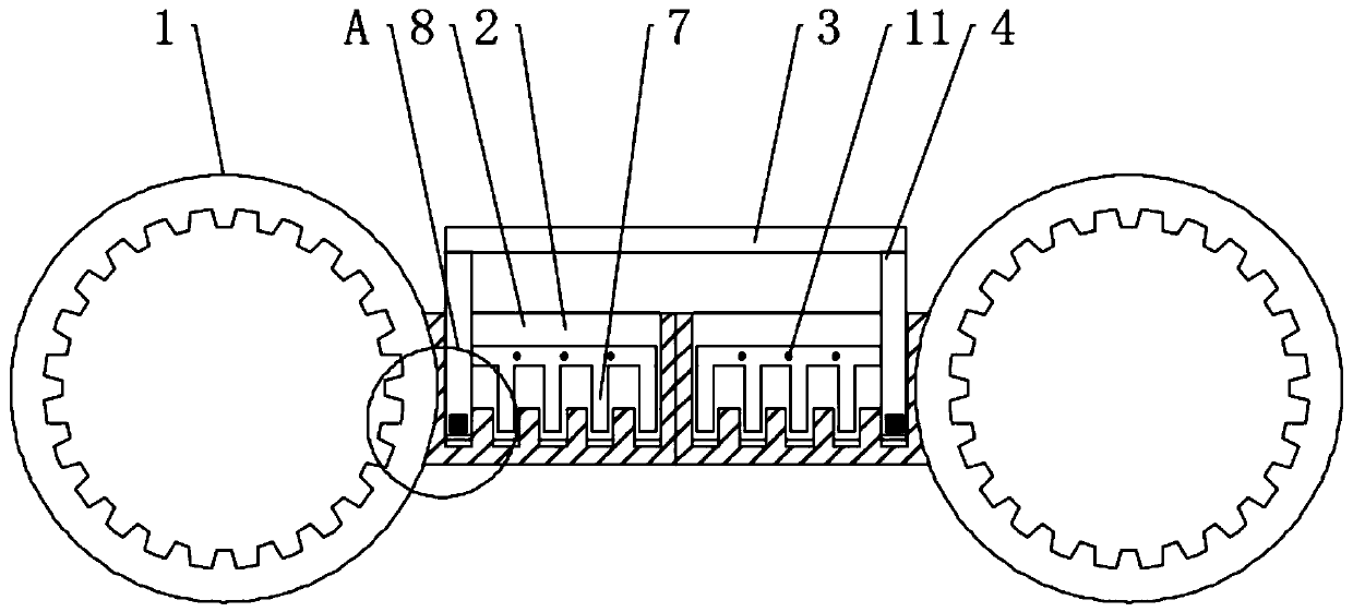
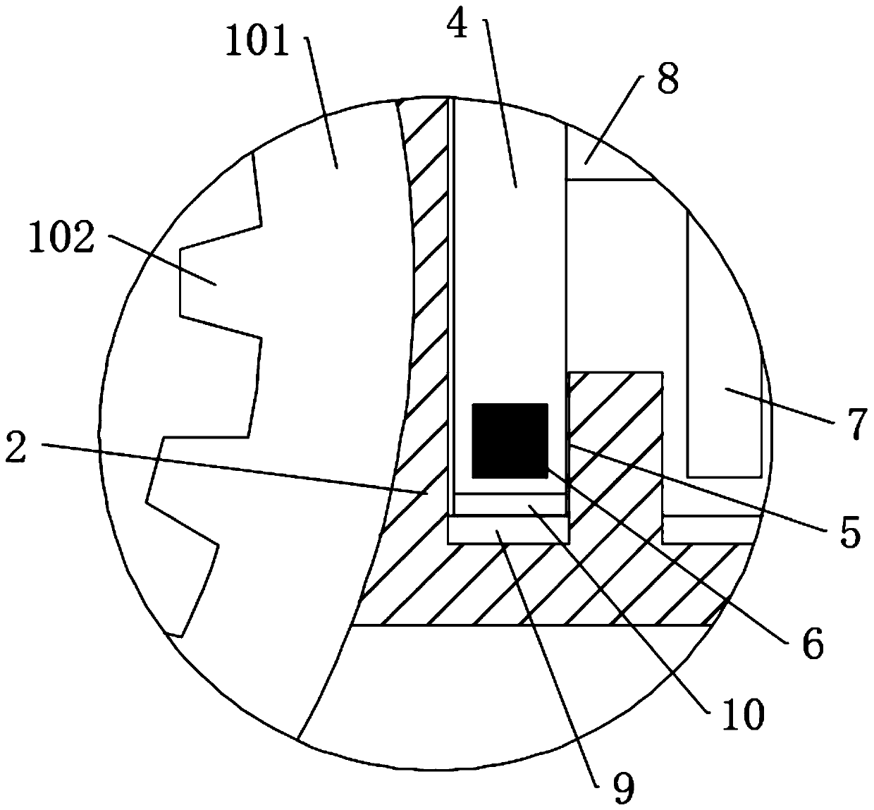
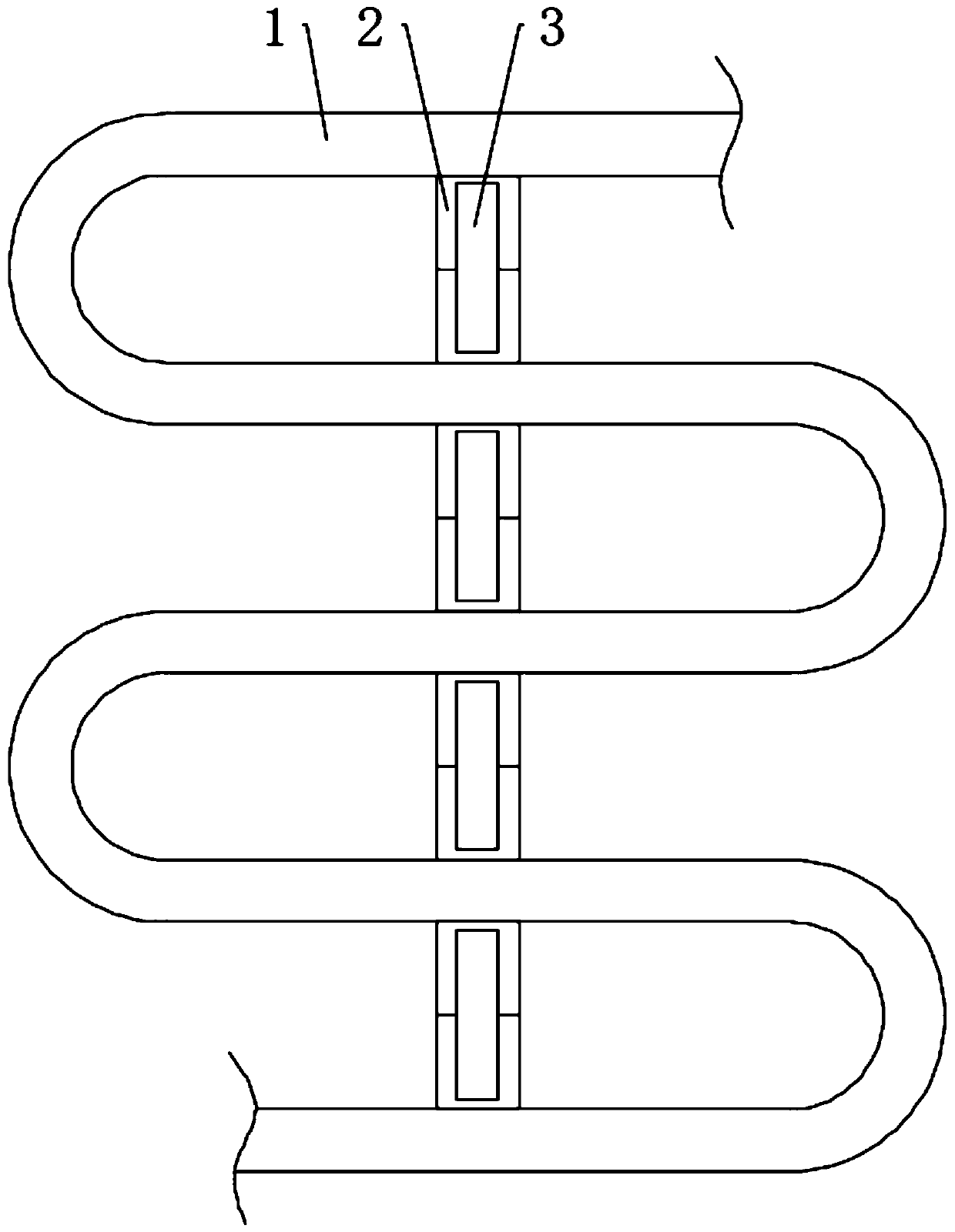
[0036] see Figure 1-3, a pipe for a water-cooling device based on electrical control, comprising a detour pipe 1, the detour pipe 1 is a plastic elastic hose, the inner end of the detour pipe 1 is fixedly connected with a heat conduction net, the heat conduction net is coated with a corrosion-resistant layer, and the heat conduction net is made of metal It is made of copper, and it is closely fitted around the inner end of the circuitous pipeline 1 at the same time, which further improves the heat conduction effect, and then improves the cooling effect of the circuitous pipeline 1. The circuitous pipeline 1 includes a pipeline body 101, and the inner end of the pipeline body 101 is fixedly connected with a number of evenly distributed inner tubes. The protrusion 102 is integrally formed between the pipe body 101 and the inner protrusion 102. Through the setting of the inner protrusion 102, the contact area between the detour pipe 1 and the cooling medium can be increased, ther...


PUM


Abstract

The invention discloses a pipeline based on electrical control for a water cooling device, and belongs to the technical field of water cooling. The pipeline based on electrical control for the water cooling device comprises a circuitous pipeline, wherein the circuitous pipeline comprises a plurality of sub-pipes arranged in a circuitous manner, the sub-pipes are integrally formed, spacer blocks are fixedly connected to one ends, close to each other, of each pair of sub-pipes, rectangular grooves are formed in the upper ends of the spacer blocks, synchronizing rods are arranged between each pair of sub-tubes, the synchronizing rods are located on the upper sides of the spacer blocks, a pair of positioning rods is fixedly connected to the lower end of each synchronizing rod, a plurality of uniformly-distributed positioning inserting grooves are formed in the bottom walls of the rectangular grooves, the positioning rods are matched with the positioning inserting grooves, limiting slidingblocks are fixedly connected to the front ends and the rear ends of the positioning rods, a plurality of vertically-distributed vertical sliding grooves are formed in the front end walls and the rearend walls of the rectangular grooves, and the vertical sliding grooves extend to the inner sides of the positioning inserting grooves. According to the pipeline, the distance between the circuitous pipelines can be adjusted according to different cooling working conditions, and the cooling efficiency and the cooling quality are improved.

Description

technical field [0001] The invention relates to the technical field of water cooling, and more specifically relates to a pipeline for a water cooling device based on electric control. Background technique [0002] The water-cooled radiator has a water inlet and a water outlet. There are multiple water channels inside the radiator, which can give full play to the advantages of water-cooled and take away more heat. This is the basic principle of the water-cooled radiator. From the installation method of water-cooled Look, it can be divided into two types: built-in water cooling and external water cooling. For built-in water cooling, it is mainly composed of radiators, water pipes, water pumps, and sufficient water sources. This means that most water cooling systems have a large "volume" and require sufficient internal space in the case. In terms of external water-cooling radiators, since the cooling water tank and water pump and other working components are all arranged outsi...

Claims


Application Information

Patent Timeline
IPC IPC(8): F28F1/40F28F27/00F28F9/013
CPCF28F1/40F28F9/013F28F27/00
Inventor 王刚唐弇冬周皓
Owner PAGMAN TECH (TAICANG) CO LTD
Why Eureka
Try Eureka